Antenna for TV do it yourself. Homemade TV antenna: for DVB and analog signal - theory, types, manufacturing. "Eight", aka rhombus, aka "Z" shaped
In life, "different things" happen. Sometimes it happens that you are even left without a TV. Moreover, the TV itself is there, but there is no antenna for it. How to receive the signal in this case? In fact, a completely effective receiver can be easily built on your own. All you need is a piece of suitable cable.

You can create a modern TV antenna DVB-T2 with your own hands from scrap materials. To do this, you need to find a 20 cm long television coaxial cable, an F type connector, and an RF connector. Of course, you will need some tools, including a tape measure, wire cutters, a knife and pliers.

Before you start making such an antenna, you should find out the broadcasting frequency in your locality. In most cases, such information is contained on the official website of the country's broadcasting company. The broadcast frequency will be indicated in MHz. It is needed in order to determine the minimum antenna length. Most often, the receiver should be in the region of 10 cm. To do this, 7,500 should be divided by the broadcasting frequency in your region (the resulting figure will be the required length).

Now we go directly to the manufacturing process. We take our 20 cm long coaxial cable and strip off 3 cm of insulation from one of its sides for the F connector. Cut the cable up to the central copper core. After that, you can screw on the connector, while the copper tail should not extend beyond it by more than 1 cm.Now we wind the HF on F, which will be connected to the plug.

Having departed 3-4 centimeters from the connector, we retreat a few more centimeters (as much as it turned out when calculating the length, depending on the broadcast frequency) and cut off the rest, the edge is stripped of insulation. The antenna itself is bent at an angle of 90 degrees for better signal reception.
Video
In the past, the site had a lot of other interesting and useful information on how to do something with your own hands. For example, here's a small guide on what happens in one way or another in life.
Once a good TV antenna was in short supply, purchased quality and durability, to put it mildly, did not differ. Making an antenna for a "box" or "coffin" (old tube TV) with your own hands was considered an indicator of skill. Interest in homemade antennas continues today. There is nothing strange here: the conditions for receiving TV have changed dramatically, and manufacturers, believing that there is nothing essentially new in the theory of antennas and will not be, most often adapt electronics to well-known designs, without thinking about the fact that the main thing for any antenna is its interaction with the signal on the air.
What has changed on the air?
Firstly, almost the entire volume of TV broadcasting is currently carried out in the UHF range... First of all, for economic reasons, it greatly simplifies and reduces the cost of the antenna-feeder system of transmitting stations, and, more importantly, the need for its regular maintenance by highly qualified specialists engaged in hard, harmful and dangerous work.
Second - TV transmitters now cover almost all more or less populated places with their signal, and a developed communication network ensures the delivery of programs to the most remote corners. There, broadcasting in the habitable zone is provided by low-power unattended transmitters.
Third, the conditions for the propagation of radio waves in cities have changed... Industrial noise leaks into the UHF weakly, but reinforced concrete high-rise buildings for them are good mirrors that repeatedly re-reflect the signal until it is completely attenuated in the zone of seemingly reliable reception.
Fourth - There are a lot of TV programs on the air now, tens and hundreds... How diverse and meaningful this is is another question, but now it makes no sense to count on the reception of 1-2-3 channels.
Finally, digital broadcasting has been developed... The DVB T2 signal is a special thing. Where it even slightly, by 1.5-2 dB, exceeds the noise, the reception is excellent, as if nothing had happened. And a little further or to the side - no, how it was cut off. The “digital” is almost not sensitive to interference, but if there is a mismatch with the cable or phase distortions anywhere in the path, from the camera to the tuner, the picture can crumble into squares even with a strong clear signal.
Antenna requirements
In accordance with the new reception conditions, the basic requirements for TV antennas have also changed:
- Its parameters, such as the directional action coefficient (directivity factor) and the protective action coefficient (COP), do not currently have a decisive significance: modern broadcast is very dirty, and according to the tiny side lobe of the directional diagram (DI), at least some kind of interference can get through, and you need to deal with it already by means of electronics.
- Instead, the antenna's own gain (KU) is of particular importance. An antenna that “catches” the ether well, and does not look at it through a small hole, will provide a power reserve for the received signal, allowing electronics to clear it of noise and interference.
- A modern television antenna, with rare exceptions, must be band-based, i.e. its electrical parameters should be preserved in a natural way, at the level of theory, and not squeezed into an acceptable framework by engineering tricks.
- The TV antenna must be matched to the cable in its entire operating frequency range without additional matching and balancing devices (USS).
- The frequency response of the antenna (AFC) should be as smooth as possible. Phase distortions are inevitably accompanied by abrupt surges and dips.
The last 3 points are due to the requirements for receiving digital signals. Customized, i.e. operating theoretically at the same frequency, antennas can be "stretched" in frequency, for example. UHF wave-channel antennas with an acceptable signal-to-noise ratio capture 21-40 channels. But their coordination with the feeder requires the use of USS, which either strongly absorb the signal (ferrite), or spoil the phase response at the edges of the range (tuned). And such an antenna, which works well on the “analog”, will receive bad reception of a “digital” antenna.
In this regard, from all the great antenna diversity, this article will consider antennas for a TV, available for self-production, of the following types:
- Frequency independent (all-wave)- does not differ in high parameters, but it is very simple and cheap, it can be done in literally an hour. Outside the city, where the air is cleaner, it may well be able to receive a digit or a sufficiently powerful analogue not a short distance from the television center.
- Range log-periodic. Figuratively speaking, it can be likened to a fishing trawl, which sorts prey when fishing. It is also quite simple, ideally matches the feeder in its entire range, absolutely does not change the parameters in it. The technical parameters are average, therefore it is more suitable for a summer residence, and in the city as a room.
- Several modifications of the zigzag antenna, or Z-antennas. In the MV range, this is a very solid construction that requires a lot of skill and time. But on the UHF, due to the principle of geometric similarity (see below), it is so simplified and shrunk that it can well be used as a highly efficient indoor antenna under almost any reception conditions.
Note: The Z-antenna, if we use the previous analogy, is a frequent nonsense, raking everything in the water. As the air was littered, it was out of use, but with the development of digital TV, it again found itself on a horse - in its entire range, it is just as perfectly coordinated and holds the parameters, like a "speech therapist".
Accurate matching and balancing of almost all antennas described below is achieved by laying the cable through the so-called. point of zero potential. It has special requirements, which will be discussed in more detail later.
About vibrator antennas
In the frequency band of one analog channel, up to several tens of digital channels can be transmitted. And, as already mentioned, the digital works with a negligible signal-to-noise ratio. Therefore, in places very far from the television center, where the signal of one or two channels barely finishes, places, for receiving digital TV, the good old wave channel (AVK, wave channel antenna), from the class of vibrator antennas, can also find application, so at the end we will devote a few lines and her.
About satellite reception
There is no point in making a satellite dish yourself. The head and the tuner still need to be bought, and behind the external simplicity of the mirror lies a parabolic surface of oblique incidence, which not every industrial enterprise can perform with the required accuracy. The only thing that homemade people can do is set up a satellite dish, about this.
About antenna parameters
An accurate determination of the above parameters of antennas requires knowledge of higher mathematics and electrodynamics, but you need to understand their meaning when starting to manufacture an antenna. Therefore, we will give a somewhat rough, but still clarifying meaning of the definition (see the figure on the right):

- KU - the ratio of the received antenna to the main (main) lobe of its DN of the signal power, to its own power, received in the same place and at the same frequency, non-directional, with a circular, BP, antenna.
- KND - the ratio of the solid angle of the entire sphere to the solid angle of the opening of the main lobe of the DN, on the assumption that its cross section is a circle. If the main lobe has different sizes in different planes, you need to compare the area of the sphere and the cross-sectional area of the main lobe.
- CPV is the ratio of the signal power received to the main lobe to the sum of the interference powers at the same frequency, received by all side (back and side) lobes.
Notes:
- If the antenna is band, the powers are calculated at the frequency of the wanted signal.
- Since there are no completely omnidirectional antennas, a half-wave linear dipole oriented in the direction of the electric field vector (according to its polarization) is taken as such. Its KU is considered equal to 1. TV programs are transmitted with horizontal polarization.
It should be remembered that CG and CPV are not necessarily interrelated. There are antennas (for example, "spy" - single-wire traveling wave antenna, ABC) with high directivity, but unity or less gain. Such people look into the distance as if through a diopter sight. On the other hand, there are antennas, eg. Z-antennas, in which low directivity is combined with significant gain.
About the intricacies of manufacturing
All elements of antennas through which currents of a useful signal flow (specifically, in the descriptions of individual antennas) must be connected to each other by soldering or welding. In any outdoor assembly, the electrical contact will soon be broken, and the parameters of the antenna will deteriorate sharply, up to its complete disrepair.
This is especially true for points of zero potential. In them, as experts say, a voltage node and a current antinode are observed, i.e. its greatest value. Zero Voltage Current? No wonder. Electrodynamics has gone from Ohm's law on direct current as far as the T-50 is from a kite.
Places with zero potential points for digital antennas are best made bent from solid metal. A small "creeping" current on welding when receiving an analogue in the picture, most likely, will not affect. But, if a digit is received at the border of noise, then the tuner may not see the signal due to "creeping". Which, with a pure current in the antinode, would give a stable reception.
About cable soldering
The braid (and often the central core) of modern coaxial cables is made not of copper, but of corrosion-resistant and inexpensive alloys. They are not soldered well and, if you heat it for a long time, you can burn the cable. Therefore, you need to solder the cables with a 40-W soldering iron, low-melting solder and flux paste instead of rosin or alcohol canin. There is no need to regret the paste, the solder immediately spreads along the veins of the braid only under a layer of boiling flux.

Antenna types
All-wave
An all-wave (more precisely, frequency independent, PNA) antenna is shown in Fig. She - two triangular metal plates, two wooden slats, and a lot of copper enameled wires. The diameter of the wire does not matter, and the distance between the ends of the wires on the rails is 20-30 mm. The gap between the plates, to which the other ends of the wires are soldered, is 10 mm.
Note: instead of two metal plates, it is better to take a square of one-sided foil-clad fiberglass in triangles cut out on copper.
The antenna width is equal to its height, the opening angle of the canvases is 90 degrees. The cable laying diagram is shown in the same place in Fig. The point marked in yellow is the quasi-zero potential point. It is not necessary to solder the cable braid to the web in it, it is enough to tie it tightly, for coordination there is enough capacity between the braid and the web.
ChNA, stretched in a window 1.5 m wide, accepts all meter and DCM channels from almost all directions, except for a dip of about 15 degrees in the plane of the canvas. This is its advantage in places where it is possible to receive signals from different telecentres, it does not need to be rotated. Disadvantages - a single CU and zero CPA, therefore, in the interference zone and outside the zone of reliable reception, the PNA is not suitable.
Note : there are other types of PNA, for example. in the form of a two-turn logarithmic spiral. It is more compact than the RNA of triangular canvases in the same frequency range, therefore it is sometimes used in technology. But in everyday life this does not give any advantages, it is more difficult to make a spiral PNA, it is more difficult to coordinate with a coaxial cable, therefore we do not consider it.
On the basis of CHNA, a very popular once fan vibrator (horns, flyer, slingshot) was created, see Fig. Its KND and KZD are something about 1.4 with a fairly smooth frequency response and linear phase response, so it would be suitable for a figure even now. But - it works only on MV (1-12 channels), and digital broadcasting goes to UHF. However, in the countryside, with a rise of 10-12 m, it may be suitable for receiving an analogue. Mast 2 can be made of any material, but the fastening strips 1 are made of a good non-wetting dielectric: fiberglass or fluoroplastic with a thickness of at least 10 mm.

Beer all-wave

The all-wave antenna from beer cans is clearly not the fruit of the hangover hallucinations of a drunken radio amateur. This is really a very good antenna for all reception situations, you just need to get it right. Moreover, it is extremely simple.
Its design is based on the following phenomenon: if the diameter of the arms of a conventional linear vibrator is increased, then the working band of its frequencies expands, while other parameters remain unchanged. Since the 1920s, the so-called. the Nadenenko dipole based on this principle. And beer cans in size are just suitable as the arms of a vibrator on a UHF. In essence, CHNA is a dipole, whose shoulders expand indefinitely to infinity.
The simplest beer vibrator of two cans is suitable for room reception of an analogue in the city, even without coordination with the cable, if its length is not more than 2 m, on the left in Fig. And if you assemble a vertical in-phase lattice from beer dipoles with a half-wave step (on the right in the figure), match it and balance it with an amplifier from the Polish antenna (we will talk about it later), then due to the vertical compression of the main lobe of the DP, such an antenna will give good ku.
The gain of the "beer" can be further increased by adding at the same time the KZD, if a screen from the grid is placed behind it at a distance equal to half the lattice spacing. The beer grate is mounted on a dielectric mast; the mechanical connections of the screen with the mast are also dielectric. The rest is clear from the trace. rice.

Note: the optimal number of lattice floors is 3-4. At 2, the gain in gain will be small, and more is difficult to match with the cable.
Video: making the simplest antenna from beer cans
"Speech therapist"
A log-periodic antenna (LPA) is a collecting line to which halves of linear dipoles are alternately connected (i.e., pieces of a conductor with a length of a quarter of the working wave), the length and distance between which change exponentially with an exponent less than 1, in the center in Fig. The line can be either configured (with a short circuit at the end opposite to the cable connection) or free. An LPA on a free (unconfigured) line for receiving a digit is preferable: it comes out longer, but its frequency response and phase response are smooth, and the matching with the cable does not depend on the frequency, so we will stop at it.

LPA can be manufactured for any, up to 1-2 GHz, pre-specified frequency range. When the operating frequency changes, its active area of 1-5 dipoles shifts back and forth along the canvas. Therefore, the closer the progression index is to 1, and, accordingly, the smaller the aperture angle of the antenna, the more gain it will give, but at the same time its length increases. On the UHF, 26 dB can be achieved from an outdoor LPA, and 12 dB from a room one.
LPA, we can say, in terms of the combination of qualities, an ideal digital antenna, therefore, let's dwell on its calculation in more detail. The main thing to know is that an increase in the progression rate (tau in the figure) gives an increase in gain, and a decrease in the LAA aperture angle (alpha) increases directivity. The screen for the LPA is not needed, it has almost no effect on its parameters.
The calculation of a digital LPA has the following features:
- They start it, for the sake of a reserve in frequency, from the second longest vibrator.
- Then, taking the reciprocal of the progression rate, calculate the longest dipole.
- After the shortest, based on the specified frequency range, dipole, add another one.
Let us explain with an example. Let's say our digital programs are in the range of 21-31 TCEs, i.e. at 470-558 MHz in frequency; wavelengths respectively - 638-537 mm. Let's also assume that we need to receive a weak noisy signal far from the station, so we take the maximum (0.9) progression rate and the minimum (30 degrees) aperture angle. To calculate, you need half the opening angle, i.e. 15 degrees in our case. The opening can be further reduced, but the length of the antenna will increase prohibitively, according to the cotangent.
We consider B2 in Fig: 638/2 = 319 mm, and the arms of the dipole will be 160 mm each, up to 1 mm can be rounded. The calculation will need to be carried out until you get Bn = 537/2 = 269 mm, and then calculate another dipole.
Now we count A2 as B2 / tg15 = 319 / 0.26795 = 1190 mm. Then, through the index of progression, A1 and B1: A1 = A2 / 0.9 = 1322 mm; B1 = 319 / 0.9 = 354.5 = 355 mm. Then, sequentially, starting with B2 and A2, we multiply by the indicator until we reach 269 mm:
- B3 = B2 * 0.9 = 287 mm; A3 = A2 * 0.9 = 1071 mm.
- B4 = 258 mm; A4 = 964 mm.
Stop, we already have less than 269 mm. We check whether we will keep within the gain, although it is already so clear that it is not: to get 12 dB or more, the distance between the dipoles should not exceed 0.1-0.12 wavelengths. In this case, we have for B1 A1-A2 = 1322 - 1190 = 132 mm, which is 132/638 = 0.21 of the B1 wavelength. It is necessary to "tighten" the indicator to 1, to 0.93-0.97, so we try different ones until the first difference A1-A2 is halved or more. For a maximum of 26 dB, a distance between the dipoles of 0.03-0.05 wavelengths is needed, but not less than 2 dipole diameters, 3-10 mm on the UHF.
Note: the remainder of the line behind the shortest dipole, cut off, it is needed only for the calculation. Therefore, the actual length of the finished antenna is only about 400 mm. If our LPA is outdoor, this is very good: you can reduce the aperture, getting more directivity and protection from interference.
Video: antenna for digital TV DVB T2
About the line and the mast
The diameter of the tubes of the LPA line on the UHF - 8-15 mm; the distance between their axes is 3-4 diameters. Let's also take into account that thin "laces" cables give such an attenuation per meter to the UHF that all antenna-amplifying tricks will come to naught. You need to take a good coaxial for an outdoor antenna, with a sheath diameter of 6-8 mm. That is, the tubes for the line must be thin-walled, seamless. It is impossible to tie the cable to the line from the outside, the quality of the LPA will drop sharply.
It is necessary, of course, to fasten the outer LPA to the mast for the center of gravity, otherwise the small windage of the LPA will turn into a huge and shaking one. But it is also impossible to connect a metal mast directly to the line: you need to provide a dielectric insert at least 1.5 m long. The quality of the dielectric does not play a big role here, a painted and painted wood will go.
About the Delta antenna
If the UHF LPA is compatible with the amplifier cable (see below, about Polish antennas), then the shoulders of a meter dipole can be attached to the line, linear or fanlike, like a "slingshot". Then we get a universal MV-UHF antenna of excellent quality. This solution is used in the popular Delta antenna, see fig.

Antenna "Delta"
Zigzag on air
The Z-antenna with a reflector gives the gain and SPL the same as the LPA, but the main lobe of its BP is more than twice as wide horizontally. This can be important in the countryside when there is TV reception from different directions. A decimeter Z-antenna is small in terms of dimensions, which is essential for indoor reception. But its operating range is theoretically not unlimited, the frequency overlap while maintaining the parameters acceptable for the figure is up to 2.7.

The design of the MV Z-antenna is shown in Fig. the path of the cable is highlighted in red. In the same place at the bottom left - a more compact ring version, in common parlance - "spider". It clearly shows that the Z-antenna was born as a combination of a PNA with a range vibrator; there is in it something of a rhombic antenna, which does not fit into the topic. Yes, the "spider" ring does not have to be wooden, it can be a metal hoop. Spider accepts 1-12 MV channels; The DN without a reflector is almost circular.
The classic zigzag works either on 1-5, or on 6-12 channels, but for its manufacture you only need wooden slats, enameled copper wire cd = 0.6-1.2 mm and several scraps of foil-clad fiberglass, so we give the dimensions through fraction for 1-5 / 6-12 channels: A = 3400/950 mm, B, C = 1700/450 mm, b = 100/28 mm, B = 300/100 mm. At point E - zero potential, here you need to solder the braid to the metallized base plate. The dimensions of the reflector are also 1-5 / 6-12: A = 620/175 mm, B = 300/130 mm, D = 3200/900 mm.
The band Z-antenna with reflector gives a gain of 12 dB, tuned to one channel - 26 dB. To build a single-channel zigzag on the basis of a band zigzag, you need to take the side of the square of the canvas in the middle of its width at a quarter of the wavelength and recalculate all other dimensions proportionally.
Folk zigzag
As you can see, the MV Z-antenna is a rather complex structure. But its principle shows itself in all its splendor on the UHF. The UHF Z-antenna with capacitive inserts, which combines the advantages of "classics" and "spider", is so simple to make that it earned the title of national one in the USSR, see fig.

Material - copper tube or aluminum sheet with a thickness of 6 mm. The side squares are solid metal or covered with a mesh, or covered with a tin. In the last two cases, they need to be soldered along the contour. The coaxial cannot be sharply bent, so we drive it so that it reaches the side corner, and then does not go beyond the capacitive insert (side square). At point A (point of zero potential), the cable sheath is electrically connected to the canvas.
Note: aluminum is not soldered with ordinary solders and fluxes, therefore, aluminum "folk" is suitable for outdoor installation only after sealing the electrical connections with silicone, because everything in it is on screws.
Video: example of a double triangular antenna
Wave channel

Antenna wave channel (AVK), or Udo-Yagi antenna available for self-production, is capable of giving the highest KU, KND and KZD. But it can receive a digit on the UHF only on 1 or 2-3 adjacent channels, because belongs to the class of sharply tuned antennas. Its parameters outside the tuning frequency deteriorate sharply. AVK is recommended to be used with very poor reception conditions, and for each TCE to make a separate one. Fortunately, it's not very difficult - AVK is simple and cheap.
The work of AVK is based on “raking” the electromagnetic field (EMF) of the signal to the active vibrator. Outwardly small, light, with minimal windage, the AVK can have an effective aperture of tens of wavelengths of the operating frequency. Shortened and therefore having capacitive impedance (impedance) directors (directors) direct the EMF to the active vibrator, and the reflector (reflector), elongated, with inductive impedance, rejects what has slipped past to it. A reflector in AVK is needed only 1, but directors can be from 1 to 20 or more. The more there are, the higher the AVK gain, but narrower its frequency band.
From interaction with the reflector and directors, the wave impedance of the active (from which the signal is removed) vibrator drops the more, the closer the antenna is tuned to the maximum gain, and the coordination with the cable is lost. Therefore, the active dipole AVK is made looped, its initial characteristic impedance is not 73 Ohm, as in the linear one, but 300 Ohm. At the cost of reducing it to 75 Ohm, an AVK with three directors (five-element, see the figure on the right) can be tuned almost to a maximum gain of 26 dB. A typical AVK DN in the horizontal plane is shown in Fig. at the beginning of the article.
The AVK elements are connected to the boom at the points of zero potential, so the mast and boom can be of any kind. Propylene pipes are very suitable.
The calculation and adjustment of AVK for analog and digital are somewhat different. Under the analogue wave channel, you need to count on the carrier frequency of the image Fi, and under the number - in the middle of the TVK spectrum Fc. Why so - here, unfortunately, there is no place to explain. For the 21st TVC, Fi = 471.25 MHz; Fc = 474 MHz. UHF TVKs are located close to each other at 8 MHz, so their tuning frequencies for AVK are calculated simply: Fn = Fi / Fc (21 TVK) + 8 (N - 21), where N is the number of the desired channel. Ex. for 39 TVKs Fi = 615.25 MHz, and Fc = 610 MHz.
In order not to write down a lot of numbers, it is convenient to express the size of the AVK in fractions of the working wavelength (it is considered as A = 300 / F, MHz). The wavelength is usually denoted by the small Greek letter lambda, but since there is no default Greek alphabet on the Internet, we will conventionally designate it as the large Russian L.
The dimensions of the AVK optimized for the figure, according to the figure, are as follows:

- P = 0.52L.
- B = 0.49L.
- D1 = 0.46L.
- D2 = 0.44L.
- D3 = 0.43l.
- a = 0.18L.
- b = 0.12L.
- c = d = 0.1L.
If you do not need a lot of gain, but it is more important to reduce the size of the AVK, then D2 and D3 can be removed. All vibrators are made from a tube or rod with a diameter of 30-40 mm for 1-5 TVK, 16-20 mm for 6-12 TVK and 10-12 mm for UHF.
AVK requires precise coordination with the cable. It is the careless implementation of the matching and balancing device (OSS) that explains most of the failures of amateurs. The simplest USS for AVK is a U-loop from the same coaxial cable. Its construction is clear from fig. on right. The distance between signal terminals 1-1 is 140 mm for 1-5 TVK, 90 mm for 6-12 TVK and 60 mm for UHF.
Theoretically, the knee length l should be half the working wavelength, and this is what most publications on the Internet say. But the EMI in the U-loop is concentrated inside the cable filled with insulation, so it is imperative (especially for a digit) to take into account its shortening factor. For 75-ohm coaxials, it ranges from 1.41 to 1.51, i.e. l you need to take from 0.355 to 0.330 wavelengths, and take it exactly so that the AVK is an AVK, and not a set of glands. The exact value of the shortening factor is always included in the cable certificate.
Recently, the domestic industry began to produce reconfigurable AVK for numbers, see fig. The idea, I must say, is excellent: by moving the elements along the arrow, you can fine-tune the antenna to the local reception conditions. It is better, of course, for a specialist to do this - the element-by-element adjustment of the AVK is interdependent, and the amateur will certainly get confused.

About "Poles" and amplifiers
For many users, Polish antennas, which previously received an analogue decently, refuse to take the figure - it breaks, or even disappears altogether. The reason, I beg your pardon, is a bawdy commercial approach to electrodynamics. Sometimes it is a shame for colleagues who have slapped such a "miracle": the frequency response and frequency response are similar either to a psoriasis hedgehog, or a horse comb with broken teeth.
The only good thing about the "Poles" is their antenna amplifiers. Actually, they do not let these products die ingloriously. Amplifiers "poles", firstly, low-noise broadband. And, more importantly, with a high impedance input. This allows, at the same intensity of the EMF signal on the air, to supply the tuner with several times its power at the input of the tuner, which makes it possible for the electronics to "rip" the figure out of the very ugly noise. In addition, due to the high input impedance, the Polish amplifier is an ideal OSS for any antennas: whatever you hook to the input, the output is exactly 75 ohms without reflection and creep.
However, with a very bad signal, outside the range of reliable reception, the Polish amplifier no longer pulls. Power is supplied to it via a cable, and the power supply decoupling takes 2-3 dB of the signal-to-noise ratio, which may just not be enough for the figure to go in the very outback. Here you need a good TV signal amplifier with separate power supply. It will be located, most likely, near the tuner, and the OSS for the antenna, if required, will have to be done separately.

The diagram of such an amplifier, which showed almost 100% repeatability even when performed by novice radio amateurs, is shown in Fig. Gain control - potentiometer P1. Isolation chokes L3 and L4 are standard purchased. Coils L1 and L2 are dimensioned in the wiring diagram on the right. They are part of the signal bandpass filters, so small deviations in their inductance are not critical.
However, the installation topology (configuration) must be followed exactly! And in the same way, a metal shield is required, which separates the output circuits from other circuits.
Where to begin?
We hope that experienced craftsmen will also find some useful information in this article. And for beginners who do not yet feel the air, it is best to start with the beer antenna. The author of the article, by no means an amateur in this area, was at one time quite surprised: the simplest "pub" with ferrite matching, as it turned out, and MV takes no worse than the tested "slingshot". And what is worth doing both - see the text.
(2
estimates, average: 4,00
out of 5)
And on the roof there was a satisfactory reception for a Pole. I have 70 - 80 kilometers to the TV center. These are my problems. From the balcony it is possible to catch from 30 channels pieces 3 - 4, and then with "cubes". Sometimes I watch TV channels from the Internet on the computer in my room, and my wife cannot watch her favorite channels normally on her TV. Neighbors advise to install cable, but you have to pay for it every month, and I already pay for the Internet, and the pension is not rubber. We pull it all, pull it, and it’s not enough for everything.
Pyotr Kopitonenko said:
It is not possible to put an antenna on the roof of the house, the neighbors swear that I go and break the roofing felt roofing and then their ceiling is leaking. Actually, I am very “grateful” to that economist who received a prize for economy. I came up with the idea of removing the expensive gable roof from the houses and replacing it with a flat roof covered with bad roofing material. The economist received money for saving, and people on the top floors now suffer all their lives. Water flows over their heads and onto the bed. They change the roofing material every year, and it falls into disrepair during the season. In frosty weather, it cracks and rainwater and snow flows into the apartment, even if no one walks on the roof !!!
Sergey said:
Greetings!
Thanks for the article, but who is the author (I don't see the signature)?
LPA according to the above method works fine, UHF 30 and 58 channels. Tested in the city (reflected signal) and outside the city, the distance to the transmitter (1 kW), respectively: 2 and 12 km approximately. Practice has shown that there is no urgent need for the “B1” dipole, but one more dipole before the shortest one has a significant effect, judging by the signal intensity in%. Especially in a city, where you need to catch (in my case) the reflected signal. only I made an antenna with a "short circuit", it happened, just there was no suitable insulator.
In general, I recommend it.
Vasily said:
IMHO: people looking for an antenna for receiving ETsTV, forget about LPA. These broadband antennas were created in the second half of the 50s (!!) of the last century in order to catch foreign TV centers on the shores of the Soviet Baltic. In magazines of that time, it was bashfully called "ultra-long-range reception." Well, they loved watching Swedish porn at night on the Riga seaside ...
In terms of appointment, I can say the same about “double, triple, etc. squares ", as well as any" zigzags ".
Compared with a "wave channel" similar in range and amplification, LPA are more cumbersome and material-intensive. The calculation of the LPA is complicated, intricate and looks more like fortune-telling and fitting the results.
If in your region, ETsTV is broadcasting on neighboring UHF channels (I have 37-38), then the best solution is to find a book on the network: Kapchinsky L.M. Television antennas (2nd edition, 1979) and make a "wave channel" for a group of UHF channels (if you broadcast more than 21-41 channels, you will have to recount) described on page 67 and further (Fig. 39, Table 11).
If up to the transmitter 15 - 30 km, the antenna can be simplified by making it four - five elements, simply without installing directors D, E and Zh.
For very close transmitters, I recommend indoor antennas, by the way, in the same book on pages 106 - 109, drawings of wide-range indoor "wave channel" and LPA are shown. The “wave channel” is visually smaller, simpler and more graceful with higher gain!
By clicking the "Add comment" button, I agree to the site.
With the development of television, an entire era has changed. The whole world has switched from analog TV to digital. This required the replacement of equipment, including television antennas. Let's figure out if it is possible to make an antenna for digital television with our own hands.
The difference between digital television broadcast antennas and analog
Digital broadcasting has several advantages over older types of television signal transmission:
- resistance to interference. Since the transmitted signal is encrypted in the form of a digital sequence of codes, it is not distorted during transmission. This allows you to get an image without interference or data loss;
- more advanced receiver. A digital television receiver, unlike analog or cable, receives information and processes it. In fact, it is a miniature computer designed for a single task;
- high image quality. The picture of digital television differs from analogue for the better. It is brighter, sharper and smoother;
- availability. Digital TV towers and repeaters are now located near most cities in Russia. This allows you to have a stable signal regardless of location.
At the same time, the procedure for connecting to digital television is quite simple. You will need to purchase hardware and configure it. You can preliminary study the coverage area of digital television in Russia at this link.
With the help of a special map, you can find out if your city is in the coverage area of digital television
Using a universal antenna for receiving digital broadcasts
To access digital television, they usually buy a special set-top box and connect a package of digital channels. In this case, the installation of the equipment is provided by a specific TV provider.
Another way is to use a universal antenna and TV tuner. Then you can connect to mainstream digital TV yourself. To do this, you need to do the following:
- Purchase a conventional universal antenna that is capable of receiving a signal in the decimeter wavelength range. If you live in an apartment of a multi-storey building, then there will probably be such an antenna on the roof; all that remains is to connect the tuner to it.
- Install the antenna on the roof. It should be directed towards the communication tower or in the opposite direction if the signal is not able to go directly to the antenna and will be reflected from the building opposite. Signal stability and image quality depend on the correct placement of the antenna.
- Turn the antenna until the image becomes clear, if it still ripples, and it is not possible to determine the angle of signal reflection. If there are many tall buildings around your home, it will be difficult to find the best option.
In addition to installing the antenna, you need to choose the right TV tuner. It is worth deciding on the additional functionality that you expect from the device. Pay attention to the following options:

Antenna for digital TV do it yourself
Making an antenna for digital television with your own hands does not require any rare materials from you. Some options are very simple and do not require special skill, while others will have to tinker with.
Simple DIY TV antennas
Let's start with simple antennas that anyone can assemble. Of course, their efficiency will be lower than that of more complex assemblies. But they will cost less.
First you need to set the required cable length. To do this, find out the broadcast frequency that you want to pick up with the antenna, and then divide 7500 by this number. As a result, you will receive the length of the antenna and will be able to start producing it:

A canned antenna can be more effective than a conventional homemade antenna. It will be able to cover a larger wavelength range and pick up more channels. To make it you will need:
- TV cable, as in the previous instructions, - it will serve as the basis for the antenna;
- hanger - it will help to strengthen the signal;
- a couple of cans;
- soldering iron - it will be needed to collect the entire structure;
- electrical tape (or scotch tape), as well as two self-tapping screws - will be needed to secure parts of the antenna.
When you collect everything you need, you can go directly to the antenna assembly process:

You can make a simple antenna out of tin cans in another way. It is best to use elongated beer cans:

Do-it-yourself sophisticated TV antennas
Complex antennas require an understanding of the design and technical skills. Moreover, the process of their assembly itself may not be more complicated than the one indicated before.
An antenna in the form of two rhombuses, fixed together in the form of a figure eight, is familiar to all radio amateurs. When assembling it, you have more freedom than in the previous versions: you can choose the material yourself, think over how to amplify the signal, and so on. General recommendations for assembling such an antenna are as follows:
- Select material. Copper or aluminum wire is optimal, although in general any tube, strip, or corner of these materials will work. Wire is the best choice simply because it is easy to shape.
- Shape the material. There should be a distance of about two centimeters between the two rhombuses that make up the figure eight. Parts of the wire can be connected using conventional pliers by applying force.
The gap between the antenna parts should be two centimeters
- Prepare the cable. It is necessary to act as in the previous instructions. Strip one end of the cable by removing the foil. Attach the cable plug to the TV.
- Attach the cable with a soldering iron to the center of the structure so that the stripped part touches both diamonds. In this case, there is no need to fix the wire along the entire eight, this will only worsen the signal quality. Be careful when using a soldering iron to avoid hurting yourself.
You can install a reflector behind the antenna
- Protect the cable from bad weather and wind. To do this, use ordinary electrical tape, and cover the soldering area with sealant. Before that, it is better to check the signal quality in order to correct the design if necessary.
A reflector can be mounted on the back, for example a parabolic dish from a curved can. This will make the signal clearer and eliminate interference.
Video: making an antenna Kharchenko with your own hands
Other antenna designs
There are many complex antennas that you can make yourself. They differ mainly in the design of the antenna body itself, which is created in order to focus the signal as much as possible. There are, for example, the following options:
- wave channel antenna. An antenna popular since Soviet times, consisting of many elements (from three and more). This design is not very effective for receiving digital television: the number of elements for its reception must reach ten, so it is better to consider other types of antennas;
Antenna made on the principle of a wave channel is not very efficient for receiving a digital signal
- antenna of the square type. An antenna that consists of several squares. Already using two, you can catch a digital signal at a short distance. If you make an antenna from three squares, then the signal will be caught much better. The upper and lower parts of the antenna have the greatest efficiency in signal reception;
Antenna of the square type is able to pick up a signal at a short distance
- antenna of six rings. Narrowband antenna that can be made from copper wire. It is known as Turkin's antenna. An antenna is not very good at filtering out interference, but it can be effective for capturing a single directional signal even at a great distance.
The ring antenna can catch and amplify the directional signal
Checking a homemade TV antenna
You can check a homemade antenna only after completing its assembly. The TV will search for digital channels automatically, so all you need to do is install the antenna correctly. This is done as follows:
- Choose a suitable place to check. The antenna should be directed towards the nearest signal repeater. Install the antenna in a suitable location.
- Turn on your TV and start a channel search. Open one of the found.
- Rotate the DIY antenna until the signal is as stable as possible. The image should stop rippling or interruption.
- If it is not possible to catch a direct signal, try to focus on the reflected one by turning the antenna in the direction opposite to the repeater.
- If the signal has not become clear, all that remains is to adjust the design and make a new attempt.
If you mount the antenna on a mast, the signal quality will improve. But at the same time, you must definitely take care of the lightning rod.
When going on vacation to a country house, sometimes, in addition to enjoying an excellent view from the window and fresh air, you want to please yourself with your favorite analog TV program, but this requires an antenna that you can make with your own hands. However, this area, unlike the city, cannot boast of a good TV signal. In such cases, available means can come to the rescue. In this article we will talk about how to make a TV antenna in artisanal conditions with your own hands.
Build an antenna yourself
What are the adaptations
There are three types of devices:
- Decimeter. The farm often uses a simpler model of such a device, this is type Z. It works great and the quality of its signal does not depend on weather conditions.
- Log-periodic. This arrangement is fairly straightforward to implement, as it is perfectly matched to all frequency ranges. For implementation, there is no need to adhere to any certain specific dimensions, it is enough to use average technical dimensions. It can be used not only in an apartment, but also in a country house.
- All-wave. This device is also simple to perform; for such purposes, almost any available metal means are suitable. The device perfectly catches the TV signal and is quite resistant to interference. If you place it near the TV tower, you can watch analog television with it.
Also, depending on the location, there are indoor and outdoor fixtures. Indoor devices are effective only in the area of an active signal; for private buildings it is better to use television sets. Such devices are passive and active. Passive ones do not need amplification, as they amplify the received signal due to their own geometry. Active devices must be equipped with an amplifier.
In this video, we will consider how to make an antenna for TV with your own hands:
How to make a TV antenna at home
In this paragraph, we will look at how to make a simple TV antenna with your own hands. An indoor TV antenna is a simple wave receiver, so any summer resident can make it with his own hands. For this you will need:
- metal tubes - 2 pieces;
- TV cable.
Note! Also, in order to make a TV antenna with your own hands from improvised means, you need to know the signal range of the television tower, which is located near the building.
Basically, the reception of frequencies varies in the range of 50-230 MHz, as a result of which 12 channels are formed. Each channel uses a different tube size. If the reception is carried out at a frequency of fifty megahertz, then the distance between the ends of the tubes should be equal to 273 centimeters, an error of three centimeters is permissible. On the twelfth channel, the distance between the tubes should be 66 centimeters.
Note! Detailed information about the length of the tubes, as well as diagrams of do-it-yourself television antennas, can be found on the Internet on special thematic sites.
Consider a list of possible materials for making a TV antenna with your own hands:
- two metal tubes, the diameter of which is 8-24 millimeters, the wall thickness and diameter of such devices must be the same;
- also in order to make an antenna you will need a TV cable, the resistance of which is 75 ohms, the length of such a wire is cut to the connection distance, taking into account the sagging;
- workpiece from getinax or textolite, the thickness of which is not less than five millimeters;
- fasteners with which the tubes will be installed on the holder;
- bracket, the shape of such a part should be angular, you can also use a wooden stand if it is fixed high enough;
- silicone, it will be needed to treat the material from oxidation;
- soldering set;
- insulating tape.
The workpiece you have chosen for making an all-wave antenna for a TV with your own hands must be divided into two parts, the tubes must be squeezed on both sides. Next, you need to fix the tubes at a distance from each other. This distance should be about six centimeters. The ends of the tubes must be fastened with clamps to the PCB blank, and the structure itself must be fixed vertically with a rod.
In order to connect the cable to a homemade television antenna, you should lay a ring that will be designed for a resistance of 75 ohms. The cores of the wire, which are located in the middle, should be stripped and twisted with the ends of the tubes. The connection of the braid is carried out using a copper wire and the rest of the connections too.
The ring that turned out and the rest of the wire length must be well fixed to the rack. The installation height of a homemade television antenna depends on the antenna's reception range.
TV antenna from beer cans
This design is the simplest do-it-yourself antenna for a TV.
To make a television antenna from beer cans, you will need two tin cans with a volume of 0.5 or 0.75 liters. However, before proceeding directly to making a TV antenna with your own hands from cans, you should take into account several nuances of this procedure. The main feature of this process is the presence of a high-quality television wire with a resistance of about 75 ohms.
It is also necessary to remember that the longer the cable is, the better the device will pick up the signal, which is especially important for the meter range. The signal of the UHF TV antenna with your own hands also depends on the length of the wire, but not so much.
In addition, you will need to prepare self-tapping screws, a trempel, a soldering iron, and electrical tape. You do not need a drawing for a TV antenna from beer cans, such a device is easy to make without it.
 Use beer cans to create a TV antenna
 Step-by-step instructions on how to make an antenna from beer cans with your own hands:
- The first step is to prepare the cable. To do this, you need to measure ten centimeters of the wire and make an incision. Then strip off a small section of the wire and twist it into a coil.
- Strip the inner core of the cable.
- Connect the plug to the wire, it is needed to connect the device to the TV.
- Next, fix the contacts to the beer cans, a screen is attached to one can with self-tapping screws, and a vein to the second.
- Next, the cable is connected to the receiver, for this it must be well fixed. For this purpose, you can use a wooden plank.
- To fix the jars, apply electrical tape, at this stage it is important to make sure that the jars are in one line.
A do-it-yourself television antenna from beer cans is ready. Such a device is able to receive both meter and decimeter frequency ranges.
Wire antenna
Many summer residents are wondering whether it is possible to make a television antenna out of wire and how. Can. A copper or brass wire antenna for a TV is a fairly simple design.
The wire for the home-made construction of the TV must be well stripped of insulation and connected one to the battery and the other to the TV receiver. Such a device is capable of receiving about five channels. Connecting the indoor antenna with your own hands to the battery pipe is necessary to provide a more powerful reception signal.
In order to make a homemade wire antenna you will need:
- two pieces of copper wire, the width of which is 4 millimeters and the length is 180 centimeters;
- a piece of plywood, dimensions 150x150 mm;
- drill;
- amplifier;
- the wire;
- fittings;
- self-tapping screws.
You can make such a TV antenna as follows:
- The first step is to give the wire the shape of two rhombuses, the side of which is 45 centimeters.
- Next, we fix the shapes on the base. This requires bolting the flattened end of the wire to the attachment point.
- If you use metal for the base, then you will need welding to fix the structural elements.
- Next, you should fix the amplifier and fix the wire on it.
- Then the entire structure is attached to the mast, which is easier to make from a metal pipe.
- The last step in making a TV antenna from improvised means is to process the entire device from corrosion.
HDTV device
When the listed methods do not help, many are wondering how to make a more powerful antenna for the TV. For such purposes, you can use an HDTV device, such a device is capable of receiving a signal of about 490 megahertz. You can make such a TV antenna at home from a transformer. The question of how to make it cannot be answered unequivocally, but it is still better to buy it in a store. To do this, you need the following details:
- electrical tape or tape;
- cardboard;
- glue;
- stapler;
- foil.
To perform such an operation, a scheme is used, according to which all parts are cut out from cardboard. Next, these parts need to be pasted over with foil, bent and cut.
Note! It is better to find the scheme and templates in advance on the Internet, download and print.
The first step in manufacturing a structure is to make a reflector, its length should be 35 centimeters. The reflector must be covered with foil. Further, in the middle of the part, you need to cut out two rectangles, they are necessary in order to fix the catcher.
Next, we go directly to the assembly of the structure. First, glue the reflector to the butterfly-shaped plate. This can be done with a stapler. Further, in the middle of each component, a hole is cut for the wire. Then the plug and transformer are connected. The device is ready.
Fixture for apartment
You can make a device that will be placed in the room in any of the above ways. If none of them is suitable due to the lack of the necessary parts, then you can use another option - make a device from copper wire or wire with foil winding. This design is able not only to catch TV signals, but also to function as a selective filter that prevents interference.
The device is fixed on a stand or hung on the wall. For digital television, such a device is most effective.
From all of the above, we can conclude that making an antenna for a TV at home is quite simple. This does not require special knowledge and complex preparations. It can be made from available tools in a short period of time, it is enough just to know the frequency range closer to the TV tower.
DIY antenna is a good idea. You don’t have to spend money on buying a finished product, and you don’t want to attract intruders with a beautiful plate or a solid radio installation.
If you have a private house or a summer cottage with a small garage, you can make your own TV antenna in just 20-30 minutes. TV is not only a source of information, but also a special atmosphere of comfort and home.
A television antenna is a device specially designed to receive broadcast television signals that are transmitted at frequencies from 41 to 250 MHz in the VHF band, and from 470 to 960 MHz in the UHF band.
Television antennas are of two types:
- Internal - located on top or next to the TV;
- Outdoor - installed on the roof or attic of the house.
Outdoor antennas are more difficult to manufacture and install, but such devices are necessary for adequate reception in peripheral areas remote from television stations.

Also antenna devices are divided into:
- Active ones, which are supplemented by an amplifier and require connection to an electrical power source;
- Passive, which amplify the signal only due to the design features.
An outdoor TV antenna is a device with a high input power, it has a unidirectional radiation intensity, so its far end must always look at the broadcasting station.
According to the wavelengths that TV antennas are capable of receiving, they are divided into three groups:
- MV antennas - such devices receive very long meter waves, the size of which can be from 0.5 to 1.5 m;
- UHF antennas - these devices operate in the decimeter range, in which the wavelength is in the range from 15 to 40 cm. It is in this coverage that digital television (DTV) is served;
- Broadband antennas are a hybrid design in which both MV and UHF elements are installed. Such radio installations are used to receive digital and analogue broadcasts at the same time.
![]()
Most often, the design of an external teleantenna is used, based on a log-periodic dipole matrix. Such products consist of several half-wave elements consisting of metal rods. They act as resonators in which energy is stored by radio waves, which cause electrons to move and create stable waves of oscillatory voltage. An antenna can have a different number of rod elements: the more, the higher its gain.
Another popular design used primarily for UHF reception is a reflective TV antenna. Such a device consists of a vertical metal shield with several dipole elements installed in front of it.
The TV broadcast bands that need to be covered by a single antenna are too wide in frequency, so either separate antennas or combined devices are used for the VHF and UHF bands. In such designs, there are two types of elements: long ones that catch the MV (they are located behind the antenna boom and often function as a log-periodic antenna) and short elements that catch the UHF broadcast (they are located in front of the boom).

When you listen to the radio, you notice that local channels can be easily tuned in to the FM or VHF range, but you won't be able to catch distant foreign broadcasts on them, for this you need to switch the receiver to MW and HF modes.
This suggests that meter, medium and short waves are well transmitted over long distances, while ultrashort and decimeter signals have a small coverage area. However, the lack of the UHF range, in which our digital television operates, is minimized due to two things:
- First, the presence of a large number of towers;
- Secondly, the ability of large objects to reflect the signal.
If you live in a private house next to a high-rise, then it is more correct to direct the TV antenna not to a distant tower, but to a neighboring house, which perfectly reflects waves. The right choice of direction largely determines the qualityTV signal.
Materials and calculation
How and from what objects and materials can you make an antenna at home? Let's take a look at the TOP 5 of the most interesting options:
- Powerful coaxial antenna;
- All-wave wire antenna;
- "Butterfly";
- "Eight" or zigzag;
- Antenna from beer cans.
Copper or aluminum tube, rod, or wire filament are excellent materials for making an antenna. They are malleable, bend well and keep their shape perfectly. You can use any conductive metal products: wires, corners, rods, strips, etc.

Coaxial cable has the same properties as copper, but it is much cheaper, and, in addition, coaxial is also mechanically strong, which is important precisely for the antenna structure. To save money, you can use pieces of wire that are available in your household or buy in the store in the non-liquidity section.
First of all, let's define the antenna size. The length of the antenna cable (L) is calculated depending on the broadcast frequency. For the calculation, we need two values:
- Wave speed in vacuum ≈ 300 million m / s;
- F - receiving frequency (digital TV signal frequencies are usually in the range of 500-800 MHz).
If we take the frequency parameter in MHz, then the desired value of the wavelength will be in meters. The calculated parameter of the speed of light is 300. You can calculate the wavelength in the cable using a simple formula:

Calculation example: let digital broadcasting be conducted at an average frequency of 610.5 MHz. Then the average wavelength = 300 / 610.5 = 0.491 m. This is exactly the length of the antenna loop.
To receive a digital signal, it is not necessary to accurately calculate the wavelength; you can simply make the design of the product more broadband.
Manufacturing and location
Today, all television is served in digital format, the analogue will soon be completely abandoned. Old antennas practically do not function with DVB signals, therefore it is necessary to create a decimeter antenna.
The transmission of digital TV in the DVB-T2 format is carried out in the UHF range, and since the signal is broadcast digitally, its reception will always be in good quality, or it simply will not be possible to catch it, and there will be no signal at all. Noise, distortion or a blurry picture - this is characteristic only of analog television.
DVB (Digital Video Broadcasting) coding is insensitive to electromagnetic interference, however, with heavily polluted air, signal mismatch may occur in it, due to which the image may freeze or completely crumble. Therefore, it is more efficient to bring the antenna outside the house: outside the window, on the roof, on the balcony.

To reduce the amount of interference, a reflector (reflector) can be built behind the antenna. For the antenna structure, the simplest materials with a metallized tinting are suitable: foil, packaging for coffee or juice, a tin can, a CD, etc. In order for the reflector to have a narrowly directed action, the shape of the reflector can be made parabolic. Although this is more relevant for analog receivers, reflectors also help out with a weak digital signal.
And the last tip: experienced engineers recommend soldering all antenna connections, and not just twisting or screwing, as over time they will oxidize and affect the reception quality. It is better to cover external antennas made by yourself with paint, it will more reliably protect your structure from adverse weather factors.
To connect the antenna elements, it is better to use soldering machines with a power of 36-40 watts, flux and soft solders.
Coaxial antenna
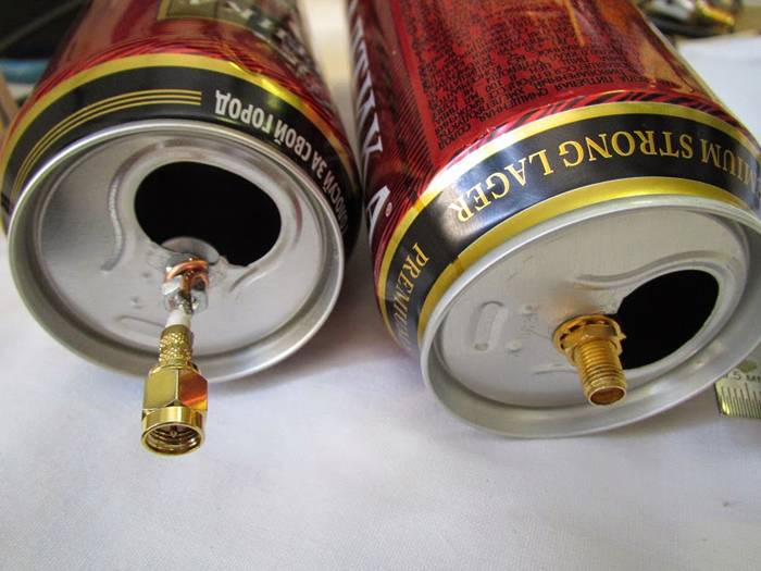
To create this version of the antenna, you will need about 0.5 m of the most common television cable marked "RK-75". One end of the insulated wire must be stripped to connect to the TV socket (the F-connector and the adapter for connecting to the TV are put on), and on the second we will create a round antenna.
Step 5 cm from the edge and remove the top layer of the insulating impregnation compound. Then remove the winding from the central conductor of the cable and twist the remaining wire strands tightly into one bundle.

From this point measure the next 22 cm and cut the outer insulation down to the shielded foil. Now you need to connect the cable into a ring: for this, the first prepared end is firmly screwed to the just created cut. That's all - you have in your hands a powerful do-it-yourself coaxial antenna.
Connect it to your TV and start channel tuning. Such an antenna is considered a good option for receiving digital television. It is better to install the antenna outside the window and from the side of the TV tower, since the walls of the building can drown out the desired signal. You can experiment with its position yourself.
All-wave antenna
A TV antenna can have different shapes. For example, a copper wire with a diameter of 2-5 mm can be used to build an all-wave antenna in the form of two versatile elements. Such devices are frequency independent, therefore they are very popular among summer residents. A CHNA device can be built in literally an hour and receive a good signal level far from television centers.
For this you will need:
- Enamelled copper wire;
- 2 metal structures in the form of an isosceles triangle;
- 2 wooden or plastic slats.
Instead of metal triangles, you can use resilient foil laminate, from which you will need to cut triangles (or leave the triangular shape of the copper coating).

The antenna width and height must be identical. The blades are installed at right angles and fixed with a soldering iron. The cable of the ChNA-antenna should be laid to the point of zero potential, which is located at the intersection of the cable with the vertical guide. Moreover, it must be tied with a coupler, and not soldered.
The distance between adjacent wire strands should be 25-30 mm, and between the plates - no more than 10 mm. It is better to install the antenna structure inside a 150 cm window. The signal catcher in the form of two expanded elements, which you just made yourself, will confidently receive all UHF and MV channels. If you live in an area with a poor signal level, it would be advisable to supplement such a device with an amplifier.
Simple antenna for receiving digital TV
Another useful type of home antenna for the dacha is the "butterfly". This is a completely uncomplicated design, for the creation of which you will need:
- Board or plywood about 60 cm long and 7 cm wide, thickness about 20 mm;
- Copper shielded wire with 4 mm conductor cross-section;
- Coaxial cable "RK-75";
- Washers, screws, soldering iron.
Below we give a marking scheme, according to which you need to make the base of the butterfly antenna.

After that, prepare 8 pieces of copper wire, each length is 37.5 cm. Step back 17.75 cm and remove 2 cm of the insulating layer in the center of each piece. Give them a V-shape so that the ends of the elements are at a distance of 7.5 cm from each other (this shape is considered optimal for high-quality and clear TV signal reception).
The next step is to prepare two more wire elements about 22 cm long. Mark each element into 3 equal parts and strip the wire insulation between the obtained pieces.
We need two more small pieces of wire in order to connect the antenna to the socket.
Now all that remains is to assemble all the prepared elements into a single structure and solder the cable to the plug.
This is how you can easily make your own effective butterfly antenna for receiving digital television broadcasting.
Antenna "eight"
The next option for creating a simple television antenna of the decimeter range has its name from the shape of its design "eight" or "zigzag". Such a device will reliably pick up a signal even in a remote village.
In order to make an outdoor antenna for digital television with your own hands, you will need:
- Amplifier (you can use any old one);
- 2 pieces of copper wire (180 cm each);
- Plate (wood or metal) 15 * 15;
- TV cable;
- An iron mast for elevating the antenna.

First of all, we create the body of the trap: from copper wire we form two rhombuses with an optimal side size of 45 cm each. We attach the ends of the two elements to the plate: we form a ring from the core and slightly flatten it, fasten it with bolts or solder it with a soldering machine.
We connect the amplifier and insert the cable plug into the connector. In general, that's it. It remains to install the finished structure on an elevated mast, which must be reliably dug into the ground.
For the manufacture of an outdoor antenna for a TV, any conductive material of the correct cross-section is suitable: copper or aluminum tubes, strips or a profile element with a thickness of 1 to 5 mm. The main thing is to give the antenna body the correct shape.
Antenna from beer cans
Terrestrial antenna devices can be made from many of the simple materials used in the home, even from regular soda cans. Such a mini-receiver will not be very powerful, but you can catch about 7 channels, and not only in the UHF range, but also in the longer one - MV.
There is one important condition: the cans must be flat, not ribbed, clean and dry. The essence of this design is very simple: you just need to solder 2 cans to the cable and place them on opposite sides on a wooden base.

The number of cans can be used differently, it is considered that it is optimal to create 3 or 4 lines of cans, since 1-2 lines pick up the signal weakly, and more than 5 lines are difficult to match. In addition to cans, you need to prepare the following materials:
- About 5 meters of ordinary TV cable marked "RK-75";
- Wooden or plastic base structure;
- Several screws, electrical tape, and a soldering machine.
First you need to prepare the TV cable: step back 10 cm from the edge, make a shallow cut and remove the top layer of insulation. Twist the inner braided screen into a single bundle. On the same side of the cable, remove the plastic insulation and expose the center conductor. Connect the plug to the opposite end of the cable.
Next, we will need to connect the coaxial cable to the banks. To do this, it is better to use small self-tapping screws for drywall: screw the twisted cable braid to one can, and a copper core to the second bank. For better contact, the connections can be soldered.
Now you should fix the cans on a wooden base plank. This can be done using ordinary scotch tape, electrical tape or glue gun, you can even use an ordinary clothes hanger or any flat improvised structure for this. The main thing is that the metal cans are of the same shape, of the same size (volume) and are located strictly on the same line. The distance between the tin elements, as well as the location of the antenna installation, is selected by an experimental method.
You can improve the design by creating a lattice of several lines with banks, and if there is such an opportunity, then connect an amplifier. If a homemade antenna made of beer cans stands on the street, then its elements will have to be hidden in larger plastic bottles.
The length of the cable affects signal suppression: the longer the size of the cord, the more the on-air transmission is suppressed. This is especially true for receiving meter waves.
Tuning and searching channels
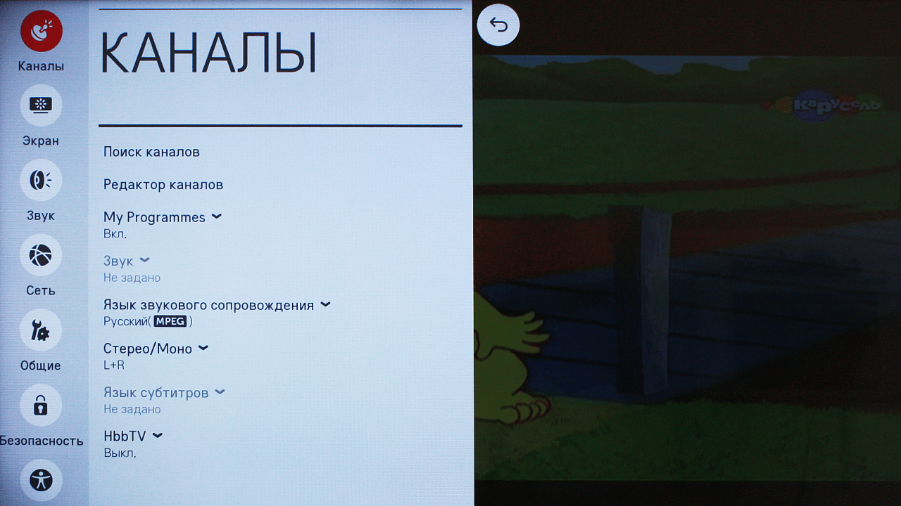
Today digital television offers us as many as 22 television channels in two packages, and in some metropolitan areas there are even more. Setting them up on your TV or set-top box will be quite simple.
In DTV air on 1 frequency, not one channel is broadcast, as it once was on analog air, but up to 10 channels in one package or multiplex. For example, on frequency 43, you can receive 10 TV channels and 3 radio stations. Therefore, a digital broadcast setting uses only 2 frequencies. However, the frequency parameter of the channels will be different for different regions.

If you use a hand-made antenna in a zone of good signal strength, then there are no special recommendations for tuning channels. You just turn on the function on your TV "Automatic channel search" and the receiver finds all available digital and analogue channels.
If the area of your location is not too favorable for TV broadcasting, and autosearch did not give results, then you need to perform the following actions:
- Check which way your antenna is facing. It should be facing the TV tower or directed to the nearest high-rise building. If you don't know which way the broadcast base is, pay attention to the antennas of your neighbors (but do not look at the satellite dishes that pick up the signal from the satellites).
- In the channel setup, set the restriction: search only digital channels (or DTV). Well, if you know the frequency parameter, then you can enter the manual channel tuning mode, dial the number of the channel on which the packet is being broadcast from the remote control, and the signal level scale in percent should appear on the display. Change the position of the antenna device and see how the stability of this indicator changes.
The change in the signal level when you turn the antenna will not change instantly, but after 5-10 seconds. Therefore, pause when changing the position of the trap.
When you get the best signal strength, search for digital channels and save the settings. Perform the same procedure to find the second multiplex. If the situation is completely sad and none of the methods yielded results, you may need to make the design of your antenna more powerful or supplement it with an amplifier.