Battery charger for lithium ion. DIY lithium battery charger. How to properly charge a polymer battery
Lithium batteries (Li-Io, Li-Po) are currently the most popular rechargeable sources of electrical energy. The lithium battery has a nominal voltage of 3.7 volts, which is indicated on the case. However, a 100% charged battery has a voltage of 4.2 V, and a discharged “to zero” - 2.5 V, there is no point in discharging the battery below 3 V, firstly, it deteriorates from this, and secondly, in the range from 3 to 2.5 Only a couple of percent of the energy is transferred to the battery. Thus, the operating voltage range is taken to be 3 - 4.2 Volts. You can watch my selection of tips for using and storing lithium batteries in this video.
There are two options for connecting batteries, serial and parallel.
With a series connection, the voltage on all batteries is summed up, when the load is connected, a current equal to the total current in the circuit flows from each battery, in general, the load resistance sets the discharge current. You must remember this from school. Now comes the fun part, the capacity. The capacity of the assembly with such a connection is good equal to the capacity of the battery with the smallest capacity. Let's assume that all batteries are 100% charged. Look, the discharge current is the same everywhere, and the battery with the smallest capacity will be discharged first, this is at least logical. And as soon as it is discharged, it will no longer be possible to load this assembly further. Yes, the rest of the batteries are still charged. But if we continue to remove the current, then our weak battery will start to over discharge and fail. That is, it is correct to assume that the capacity of a series-connected assembly is equal to the capacity of the smallest or most discharged battery. From here we conclude: firstly, you need to collect a serial battery from batteries of the same capacity, and secondly, before assembly, they must all be charged the same way, in other words, 100%. There is such a thing called BMS (Battery Monitoring System), it can monitor each battery in the battery, and as soon as one of them is discharged, it disconnects the entire battery from the load, this will be discussed below. Now with regard to charging such a battery. You need to charge it with a voltage equal to the sum of the maximum voltages on all batteries. For lithium, this is 4.2 volts. That is, we charge a battery of three with a voltage of 12.6 V. See what happens if the batteries are not the same. The battery with the smallest capacity will charge the fastest. But the rest are still not charged. And our poor battery will fry and recharge until the rest are charged. Overdischarge, I remind you, lithium also does not like very much and deteriorates. To avoid this, we recall the previous conclusion.
Let's move on to parallel connection. The capacity of such a battery is equal to the sum of the capacities of all the batteries included in it. The discharge current for each cell is equal to the total load current divided by the number of cells. That is, the more Akum in such an assembly, the more current it can deliver. An interesting thing happens with tension. If we collect batteries that have different voltages, that is, roughly speaking, charged to different percentages, then after connection they will begin to exchange energy until the voltage on all cells becomes the same. We conclude: before assembling the Akum, they must again be charged in the same way, otherwise, when connected, large currents will flow, and the discharged Akum will be damaged, and most likely it may even catch fire. In the process of discharging, the batteries also exchange energy, that is, if one of the cans has a smaller capacity, the rest will not allow it to discharge faster than themselves, that is, batteries with different capacities can be used in parallel assembly. The only exception is work at high currents. On different batteries under load, the voltage sags in different ways, and between the “strong” and “weak” Akum, the current will start to run, but we do not need this at all. And the same goes for charging. You can absolutely safely charge batteries of different capacities in parallel, that is, balancing is not needed, the assembly will balance itself.
In both cases considered, the charging current and the discharge current must be observed. The charging current for Li-Io should not exceed half the battery capacity in amperes (1000 mah battery - charge 0.5 A, battery 2 Ah, charge 1 A). The maximum discharge current is usually indicated in the datasheet (TTX) of the battery. For example: laptop 18650s and batteries from smartphones cannot be loaded with a current exceeding 2 battery capacities in Amperes (example: Akum for 2500 mah, which means that you need to take a maximum of 2.5 * 2 = 5 Amperes from it). But there are high-current batteries, where the discharge current is clearly indicated in the characteristics.
Features of charging batteries with Chinese modules
Standard commercially available charging and protection module for 20 rubles for lithium battery ( link to Aliexpress)
(positioned by the seller as a module for one 18650 cell) can and will charge any lithium battery regardless of shape, size and capacity to the correct voltage of 4.2 volts (voltage of a fully charged battery, to the eyeballs). Even if it's a huge 8000mah lithium package (of course, we are talking about one 3.6-3.7v cell). The module provides a charging current of 1 amp, this means that they can safely charge any battery with a capacity of 2000mah and above (2Ah, which means the charging current is half the capacity, 1A) and, accordingly, the charging time in hours will be equal to the battery capacity in amperes (in fact, a little more, one and a half to two hours for every 1000mah). By the way, the battery can be connected to the load already during charging.
Important! If you want to charge a battery with a smaller capacity (for example, one old 900mah can or a tiny 230mah lithium bag), then the charging current of 1A is a lot, it should be reduced. This is done by replacing the resistor R3 on the module according to the attached table. The resistor is optional smd, the most common one will do. Let me remind you that the charging current should be half of the battery capacity (or less, no big deal).
But if the seller says that this module is for one 18650 can, can they charge two cans? Or three? What if you need to assemble a capacious power bank from several batteries?
CAN! All lithium batteries can be connected in parallel (all pluses to pluses, all minuses to minuses), REGARDLESS OF CAPACITY. Batteries soldered in parallel maintain an operating voltage of 4.2v and their capacity is added. Even if you take one can at 3400mah and the second at 900, you get 4300. The batteries will work as a whole and will discharge in proportion to their capacity.
The voltage in a PARALLEL assembly is ALWAYS THE SAME ON ALL BATTERIES! And not a single battery can be physically discharged in an assembly earlier than others, the principle of communicating vessels works here. Those who argue the opposite and say that batteries with a lower capacity will discharge faster and die - they confuse it with SEQUENTIAL assembly, spit in their faces.
Important! Before connecting to each other, all batteries must have approximately the same voltage, so that at the moment of soldering, equalizing currents do not flow between them, they can be very large. Therefore, it is best to simply charge each battery separately before assembling. Of course, the charging time of the entire assembly will increase, since you are using the same 1A module. But you can parallelize two modules, getting a charging current of up to 2A (if your charger can give that much). To do this, connect with jumpers all the analogous terminals of the modules (except for Out- and B +, they are duplicated on the boards by other dimes, and will be connected anyway). Or you can buy a module ( link to Aliexpress), on which the microcircuits are already in parallel. This module is capable of charging with a current of 3 Amperes.
Sorry for the obvious, but people are still confused, so we have to discuss the difference between parallel and serial.
PARALLEL the connection (all pluses to pluses, all minuses to minuses) maintains the battery voltage of 4.2 volts, but increases the capacity by adding all the capacities together. All power banks use a parallel connection of several batteries. Such an assembly can still be charged from USB and the voltage rises to the output 5v with a step-up converter.
CONSECUTIVE the connection (each plus to minus of the subsequent battery) gives a multiple increase in the voltage of one charged 4.2v can (2s - 8.4v, 3s - 12.6v, and so on), but the capacity remains the same. If three 2000mah batteries are used, then the assembly capacity is 2000mah.
Important! It is believed that for sequential assembly it is sacred to use only batteries of the same capacity. In fact, this is not the case. You can use different ones, but then the battery capacity will be determined by the LOWEST capacity in the assembly. Add 3000 + 3000 + 800 - you get 800mah assembly. Then the specialists begin to crow, that then the less capacious battery will discharge faster and die. It doesn't matter! The main and truly sacred rule is that for consistent assembly it is always and absolutely necessary to use the BMS protection board for the required number of cans. It will determine the voltage on each cell and turn off the entire assembly if any discharges first. In the case of a bank for 800, it will be discharged, the BMS will disconnect the load from the battery, the discharge will stop and the residual charge of 2200mah on the remaining banks will no longer matter - you need to charge.
The BMS board, in contrast to the single charging module, IS NOT a CHARGER for sequential assembly. To charge you need configured source of the required voltage and current... Guyver made a video about this, so do not waste time, watch it, there it is about it as thoroughly as possible.
Can a daisy chain be charged by connecting multiple single charging modules?
In fact, with some assumptions, it is possible. For some homemade products, the scheme has proven itself using single modules, also connected in series, but EACH module needs its own SEPARATE POWER SUPPLY. If you charge 3s - take three phone chargers and connect each one to one module. When using one source - power short circuit, nothing works. Such a system also works as a protection of the assembly (but the modules are capable of delivering no more than 3 amperes) Or, simply charge the assembly in batches, connecting the module to each battery until it is fully charged.
Battery charge indicator
It is also an urgent problem - at least to know approximately how many percent of the charge remains on the battery so that it does not discharge at the most crucial moment.
For parallel assemblies at 4.2 volts, the most obvious solution would be to immediately purchase a ready-made powerbank board, which already has a display showing the percentage of charge. These percentages are not super-accurate, but they still help. The price of the issue is about 150-200 rubles, all are presented on Guyver's website. Even if you are collecting not a powerbank, but something else, this board is quite cheap and small to place it in a homemade product. Plus, it already has the function of charging and protecting batteries.
There are ready-made miniature indicators for one or several cans, 90-100r
Well, the cheapest and most popular method is to use an MT3608 step-up converter (30 rubles), tuned to 5-5.1v. Actually, if you make a power bank on any 5-volt converter, then you don't even need to buy anything. The revision consists in installing a red or green LED (other colors will work at a different output voltage, from 6V and above) through a 200-500 ohm current-limiting resistor between the output positive terminal (this will be a plus) and the input positive (for the LED it will turn out to be a minus). You are not mistaken, between two pluses! The fact is that when the converter is operating, a voltage difference is created between the pluses, +4.2 and + 5v give each other a voltage of 0.8v. When the battery is discharged, its voltage will drop, and the output from the converter is always stable, which means the difference will increase. And when the voltage on the bank is 3.2-3.4v, the difference will reach the required value to light the LED - it starts to show that it is time to charge.
How to measure the capacity of batteries?
We are already accustomed to the opinion that Aimax b6 is needed for measurement, but it costs money and is redundant for most radio amateurs. But there is a way to measure the capacity of a 1-2-3 can battery with sufficient accuracy and cheap - a simple USB tester.
Inventions and use of tools with self-contained power supplies have become one of the hallmarks of our time. New active components are being developed and introduced to improve the performance of battery assemblies. Unfortunately, the batteries cannot work without recharging. And if on devices with constant access to the power grid, the issue is solved by built-in sources, then for powerful power sources, for example, a screwdriver, separate chargers for lithium batteries are needed, taking into account the peculiarities of various types of batteries.
In recent years, products based on a lithium-ion active component have been increasingly used. And this is quite understandable, since - how these power supplies have proven themselves from a very good side:
- they have no memory effect;
- self-discharge is almost completely eliminated;
- can work at subzero temperatures;
- hold the discharge well.
- the number brought to 700 cycles.
But, each type of battery has its own characteristics. So, the lithium-ion component requires the design of elementary batteries with a voltage of 3, 6V, which requires some individual features for such products.
Recovery features
With all the advantages of lithium-ion batteries, they have their disadvantages - this is the possibility of internal closure of the cells during overvoltage charging due to active crystallization of lithium in the active component. There is also a limitation on the minimum voltage value, which makes it impossible for the active component to receive electrons. To eliminate the consequences, the battery is equipped with an internal controller, which breaks the circuit of the cells with the load when critical values are reached. Such cells are stored best when charging 50% at +5 - 15 ° C. Another feature of lithium-ion batteries is that the battery life depends on the time it was made, regardless of whether it was in use or not. or in other words, it is subject to the "aging effect", which limits its useful life to five years.
Charging Lithium Ion Batteries

The simplest single cell charger
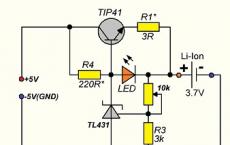
In order to understand more complex schemes for charging lithium-ion batteries, consider a simple charger for lithium batteries, more precisely for one battery.
The basis of the circuit leaves control: the TL 431 microcircuit (acts as an adjustable zener diode) and one reverse conduction transistor.
As you can see from the diagram, the TL431 control electrode is included in the base of the transistor. Setting up the device boils down to the following: you need to set a voltage of 4.2V at the output of the device - this is set by adjusting the zener diode by connecting to the first leg of resistance R4 - R3 with a nominal value of 2.2 kΩ and 3 kΩ. This circuit is responsible for adjusting the output voltage, the voltage adjustment is only set once and is stable.
Next, the charge current is regulated, the adjustment is made by resistance R1 (in the diagram with a nominal value of 3 Ohm) if the emitter of the transistor is turned on without resistance, then the input voltage will be at the charging terminals, that is, it is 5V, which may not meet the requirements.
Also, in this case, the LED will not light up, but it signals the current saturation process. The resistor can be rated from 3 to 8 ohms.
To quickly adjust the voltage across the load, the resistance R3 can be set adjustable (potentiometer). The voltage is adjusted without load, that is, without element resistance, with a nominal value of 4, 2 - 4.5V. After reaching the required value, it is enough to measure the value of the resistance of the variable resistor and put the main part of the required value in its place. If the required rating is not available, it can be assembled from several pieces by parallel or serial connection.
Resistance R4 is designed to open the base of the transistor, its rating should be 220 Ohm. With an increase in the battery charge, the voltage will increase, the control electrode of the base of the transistor will increase the emitter-collector contact resistance, reducing the charging current.
The transistor can be used KT819, KT817 or KT815, but then you have to install a radiator for cooling. Also, a radiator will be needed if the currents exceed 1000mA. In general, this classic scheme is the simplest charging.
Improvement of the charger for lithium li - ion batteries
When it becomes necessary to charge lithium-ion batteries connected from several soldered unit cells, it is best to charge the cells separately using a control circuit that will monitor the charging of each individual battery individually. Without this circuit, a significant deviation in the characteristics of one element in a sequentially soldered battery will lead to malfunction of all batteries, and the unit itself will even be dangerous due to its possible overheating or even ignition.
Charger for 12 volt lithium batteries. Balancer device
The term balancing in electrical engineering means a charging mode that controls each individual element involved in the process, preventing the voltage from increasing or decreasing below the required level. The need for such solutions stems from the peculiarities of assemblies with li - ion. If, due to the internal structure, one of the cells is charged faster than the others, which is very dangerous for the state of the remaining cells, and as a consequence of the entire battery. The circuitry of the balancer is made in such a way that the circuit elements take on excess energy, thereby regulating the charging process of an individual cell.
If we compare the principles of charging nickel-cadmium batteries, then they differ from lithium-ion, primarily in Ca-Ni, the end of the process is evidenced by an increase in the voltage of the polar electrodes and a decrease in the current to 0.01mA. Also, before charging, this source must be discharged at least 30% of its original capacity, if this condition is not maintained, a "memory effect" appears in the battery, which reduces the battery capacity.
The opposite is true with the Li-Ion active ingredient. Complete discharge of these cells can lead to irreversible consequences and drastically reduce the ability to charge. Often, low-quality controllers may not provide control over the level of battery discharge, which can lead to malfunctions of the entire assembly due to one cell.
A way out of the situation can be the use of the above circuit on an adjustable zener diode TL431. A load of 1000 mA or more can be provided by installing a more powerful transistor. Such cells are connected directly to each cell to prevent improper charging.

Choose a transistor based on power. Power is calculated using the formula P = U * I, where U is the voltage, I is the charging current.
For example, with 0.45 A current charging, the transistor must have a power dissipation of at least 3.65 V * 0.45A = 1.8 W. and this is a large current load for internal transitions, so it is better to install the output transistors in radiators.
Below is an approximate calculation of the value of resistors R1 and R2 for different charging voltages:
22.1k + 33k => 4.16V
15.1k + 22k => 4.20V
47.1k + 68k => 4.22V
27.1k + 39k => 4.23V
39.1k + 56k => 4.24V
33k + 47k => 4.25V
Resistance R3 is the load at the base of the transistor. Its resistance can be 471 Ohm - 1, 1 kOhm.
But, when implementing these circuit solutions, a problem arose, how to charge a separate cell in the battery pack? And such a solution was found. If you look at the contacts on the charging leg, then on the lithium-ion battery cases produced recently there are as many contacts as there are separate cells in the battery, of course, on the charger each such element is connected to a separate controller circuit.
In terms of cost, such a charger is somewhat more expensive than a linear device with two contacts, but it is worth it, especially when you consider that assemblies with high-quality lithium-ion components come up to half the cost of the product itself.
Impulse charger for lithium li - ion batteries
Recently, many leading companies - manufacturers of self-powered hand tools, widely advertise fast chargers. For these purposes, pulse converters based on pulse width modulated signals (PWM) were developed to restore power supplies for screwdrivers based on a PWM generator on a UC3842 microcircuit, a flyback AS - DS converter with a load on a pulse transformer was assembled.
Next, we will consider the operation of the circuit of the most common sources (see the attached diagram): the mains voltage of 220V is supplied to the diode assembly D1-D4, for these purposes, any diodes with a power of up to 2A are used. Ripple smoothing occurs on capacitor C1, where a voltage of about 300V is concentrated. This voltage is the power supply for the pulse generator with transformer T1 at the output.

The initial power for starting the integrated microcircuit A1 is supplied through the resistor R1, after which the microcircuit pulse generator is turned on, which outputs them to pin 6. Then, the pulses are fed to the gate of the powerful field-effect transistor VT1, opening it. The drain circuit of the transistor supplies power to the primary winding of the pulse transformer T1. After that, the transformer will turn on and the transmission of pulses to the secondary winding begins. The pulses of the secondary winding 7 - 11 after rectification by the diode VT6 are used to stabilize the operation of the A1 microcircuit, which, in full generation mode, consume much more current than it receives through the circuit from the resistor R1.
In the event of a failure of diodes D6, the source goes to the ripple mode, alternately starting the operation of the transformer and stopping it, while a characteristic pulsating "squeak" is heard, let's see the operation of the circuit in this mode.
Power through R1 and capacitor C4 starts the IC's generator. After starting, a higher current is required for normal operation. In the event of a D6 malfunction, no additional power is supplied to the microcircuit, and the generation stops, then the process is repeated. If the diode D6 is working properly, it immediately turns on the pulse transformer under full load. With a normal start of the generator, a pulse current of 12-14V appears on the winding 14-18 (at idle speed 15V). After rectification by the diode V7 and smoothing of the pulses by the capacitor C7 and the pulse current is supplied to the battery terminals.
A current of 100 mA, does not harm the active component, but increases the recovery time by 3-4 times, reducing its time from 30 minutes to 1 hour. ( source - magazine Internet edition Radioconstructor 03-2013)
Quick charger G4-1H RYOBI ONE + BCL14181H
 Pulse device for lithium batteries 18 volt manufactured by the German company Ryobi, manufacturer of the People's Republic of China. The pulse device is suitable for lithium-ion, nickel-cadmium 18V. Designed for normal operation at temperatures from 0 to 50 C. The circuit design provides two modes of voltage supply and current stabilization. The pulsed current supply ensures optimal feeding of each individual battery.
The device is made in an original case made of impact-resistant plastic. Forced cooling from a built-in fan is applied, with automatic switching on when it reaches 40 ° C.
Specifications:
- The minimum charging time of 18V at 1.5 A / h is 60 minutes, weight is 0.9 kg, dimensions: 210 x 86 x 174 mm. The indication of the charging process is illuminated by a blue LED, after the end, the red one lights up. There is a diagnostics of a malfunction, which lights up in case of an assembly malfunction with a separate backlight on the case.
- Single-phase power supply 50Hz. 220V. The length of the power cable is 1.5 meters.
Charging station repair
If it happens that the product has ceased to perform its functions, it is best to contact specialized workshops, but elementary faults can be eliminated by hand. What to do if the power indicator is off, let's look at some simple malfunctions using the station as an example.
This product is designed to operate with 12V, 1.8A Li-ion batteries. The product is made with a step-down transformer, the conversion of the reduced alternating current is performed by a four-diode bridge circuit. An electrolytic capacitor is installed to smooth out the ripple. From the indication there are LEDs for mains supply, beginning and end of saturation.
So, if the network indicator is off. First of all, it is necessary, through the power plug, to make sure that the primary winding of the transformer is intact. To do this, through the pins of the mains power plug, you need to ring the integrity of the primary winding of the transformer with an ohmmeter by touching the instrument's probes to the pins of the mains plug, if the circuit shows an open, then you need to inspect the parts inside the case.
The fuse may break, usually it is a thin wire stretched in a porcelain or glass case, which burns out during overloads. But some firms, for example, "Interskol", in order to protect the transformer windings from overheating, install a thermal fuse between the turns of the primary winding, the purpose of which, when the temperature reaches 120 - 130 ° C, to break the power supply circuit of the network and, unfortunately, it after the break does not restore.
Usually the fuse is located under the cover paper insulation of the primary winding, after opening which, you can easily find this part. To bring the circuit back into working condition, you can simply solder the ends of the winding into one piece, but you need to remember that the transformer remains without short-circuit protection and it is best to install a conventional mains fuse instead of a thermal fuse.
If the primary winding circuit is intact, the secondary winding and diodes of the bridge ring out. For continuity of diodes, it is better to remove one end from the circuit and check the diode with an ohmmeter. When connecting the ends to the terminals of the probes alternately in one direction, the diode should show an open circuit, in the other, a short circuit.
Thus, it is necessary to check all four diodes. And, if, already, we got into the circuit, then it is best to immediately change the capacitor, because the diodes are usually overloaded due to the high electrolyte in the capacitor.
Buy power supplies for a screwdriver
Any hand tools and batteries can be purchased on our website. To do this, you need to go through a simple registration procedure and then follow the simple navigation. Simple site navigation will easily lead you to the tool you need. On the site you can see the prices and compare them with competing stores. Any question that arises can be resolved with the help of the manager, by calling the specified phone number or leaving a question to the specialist on duty. Visit us and you will not be left without choosing the tool you need.
The purpose of this article is to learn how to use conventional laboratory power supplies to charge lithium-ion rechargeable batteries when a dedicated charger is not available. Such batteries are very common, but not everyone can (or wants) to buy a charger for its competent charging, often charging them with ordinary regulated power supplies. Let's take a look at how to do this.
Take Panasonic's ncr18650b 3.6 V 3400 mah lithium-ion battery as an example. We warn you right away that charging this type of battery is quite dangerous if you do it wrong. Some examples of bullying withstand, and some Chinese "super-economical" do not have protection and can explode.
Protected battery
A protected battery must have the following protection features:
- PTC, protection against overheating and, indirectly, over current.
- CID, the pressure valve, will shut off the cell if the pressure is high inside, which may occur due to overcharging.
- PCB, over-discharge protection board, reset is done automatically or when placed in the charger.
The above figure shows how the jar protection works. This design is used for any type of modern rugged lithium-ion battery. The PTC and pressure valve will not be visible as it is part of the original battery, but all other parts of the protection can be seen. Below are shown the variants of electronic protection modules, which are most often found in standard round Li-Ion batteries.

Lithium charging
You can find the typical circuit and charging principle for ncr18650b batteries in the datasheet. According to the documentation, the charging current is 1600 mA and the voltage is 4.2 volts.

The process itself consists of two stages, the first is direct current, where it is necessary to set the value to 1600 mA DC, and when the battery voltage reaches 4.20 V, the second stage begins - constant voltage. At this stage, the current will drop slightly, and about 10% of the charging current will flow from the charger - this is about 170 mA. This manual applies to all non-18650 lithium-ion and lithium-polymer batteries.


It is difficult to manually set and maintain the above modes on a regular power supply, so it is better to use special microcircuits designed to automate the charging process (see the diagrams in this section). As an extreme case, you can charge with a stable current of 30-40% of the full (passport) capacity of the battery, skipping the second stage, but this will somewhat reduce the life of the element.
Charger circuits
elwo.ru
Li-ion battery discharge indicator circuits to determine the charge level of a lithium battery (for example, 18650)
 What could be sadder than a suddenly dead battery in a quadcopter during a flight or a turned off metal detector in a promising meadow? Now, if only it would be possible to know in advance how strongly the battery is charged! Then we could plug in the charger or put in a new set of batteries without waiting for the sad consequences.
And just here the idea is born to make some kind of indicator that will give a signal in advance that the battery will soon run out. Radio amateurs all over the world were puffing over the implementation of this task, and today there is a whole carriage and a small cart of various circuitry solutions - from circuits on one transistor to sophisticated devices on microcontrollers.
Attention! The circuits given in the article only signal a low voltage on the battery. To prevent deep discharge, you must manually disconnect the load or use discharge controllers.
Option number 1
Let's start, perhaps, with a simple circuit on a zener diode and a transistor: 
Let's see how it works.
As long as the voltage is above a certain threshold (2.0 Volts), the zener diode is in breakdown, respectively, the transistor is closed and all the current flows through the green LED. As soon as the voltage on the battery begins to fall and reaches a value of the order of 2.0V + 1.2V (voltage drop at the base-emitter junction of transistor VT1), the transistor starts to open and the current begins to redistribute between both LEDs.
If we take a two-color LED, then we get a smooth transition from green to red, including the entire intermediate range of colors.
Typical forward voltage difference in bi-color LEDs is 0.25 Volts (red is lit at lower voltage). It is this difference that determines the area of complete transition between green and red.
Thus, in spite of its simplicity, the circuit allows you to know in advance that the battery has started to run out. While the battery voltage is 3.25V or more, the green LED is on. Between 3.00 and 3.25V, red begins to mix with green - the closer to 3.00 Volts, the more red. Finally, at 3V, only pure red is lit.
The disadvantage of the circuit is the complexity of the selection of zener diodes to obtain the required operation threshold, as well as the constant current consumption of the order of 1 mA. Well, it is possible that color blind people will not appreciate this idea with changing colors.
By the way, if you put a transistor of a different type in this circuit, it can be made to work in the opposite way - the transition from green to red will occur, on the contrary, in the event of an increase in the input voltage. Here's a modified circuit: 
Option number 2
The following circuit uses the TL431, a precision voltage regulator. 
The response threshold is determined by the voltage divider R2-R3. With the ratings indicated in the diagram, it is 3.2 Volts. When the voltage on the battery drops to this value, the microcircuit stops shunting the LED and it lights up. This will be a signal that the full discharge of the battery is very close (the minimum allowable voltage on one li-ion bank is 3.0 V).
If the device is powered by a battery from several series-connected lithium-ion batteries, then the above circuit must be connected to each bank separately. In this way: 
To set up the circuit, we connect an adjustable power supply instead of batteries and, by selecting the resistor R2 (R4), we achieve the ignition of the LED at the moment we need.
Option number 3
And here is a simple diagram of a li-ion battery discharge indicator on two transistors:  The response threshold is set by the resistors R2, R3. Old Soviet transistors can be replaced with BC237, BC238, BC317 (KT3102) and BC556, BC557 (KT3107).
Option number 4
A circuit based on two field-effect transistors, which literally consumes microcurrents in standby mode. 
When the circuit is connected to a power source, a positive voltage at the gate of the transistor VT1 is formed using the divider R1-R2. If the voltage is higher than the cutoff voltage of the field-effect transistor, it opens and attracts the gate VT2 to ground, thereby closing it.
At a certain moment, as the battery is discharged, the voltage taken from the divider becomes insufficient to unlock VT1 and it closes. Consequently, a voltage appears at the gate of the second field worker, which is close to the supply voltage. It opens and lights up the LED. The glow of the LED signals us about the need to recharge the battery.
Transistors will do any n-channel with low cutoff voltage (the less the better). The performance of the 2N7000 has not been tested in this circuit.
Option number 5
On three transistors: 
I think the diagram is self-explanatory. Thanks to the large coeff. amplification of three transistor stages, the circuit works very clearly - a difference of 1 hundredth of a volt is enough between a lit and unlit LED. The current consumption with the indication on is 3 mA, with the LED off - 0.3 mA.
Despite the bulky appearance of the circuit, the finished board has a rather modest size: 
From the VT2 collector, you can take a signal that allows the load to be connected: 1 - allowed, 0 - prohibited.
Transistors BC848 and BC856 can be replaced by BC546 and BC556, respectively.
Option number 6
I like this circuit in that it not only turns on the indication, but also cuts off the load. 
The only pity is that the circuit itself does not turn off from the battery, continuing to consume energy. And she eats, thanks to the constantly burning LED, a lot.
In this case, the green LED acts as a reference voltage source, consuming a current of about 15-20 mA. To get rid of such a voracious element, instead of an exemplary voltage source, you can use the same TL431, turning it on according to the following scheme *: 
* connect the cathode TL431 to the 2nd pin of the LM393.
Option number 7
A circuit using so-called voltage monitors. They are also called supervisors and voltage detectors (voltdetectors). These are specialized microcircuits designed specifically for voltage control.
For example, here is a circuit that lights up an LED when the voltage on the battery drops to 3.1V. Assembled on BD4731. 
Agree, it couldn't be easier! The BD47xx has an open collector output and also self-limits the output current to 12 mA. This allows you to connect an LED directly to it, without limiting resistors.
Similarly, you can apply any other supervisor to any other voltage.
Here are a few more options to choose from:
- at 3.08V: TS809CXD, TCM809TENB713, MCP103T-315E / TT, CAT809TTBI-G;
- at 2.93V: MCP102T-300E / TT, TPS3809K33DBVRG4, TPS3825-33DBVT, CAT811STBI-T3;
- series MN1380 (or 1381, 1382 - they differ only in the case). For our purposes, the option with an open drain is best suited, as evidenced by the additional number "1" in the designation of the microcircuit - MN13801, MN13811, MN13821. The trigger voltage is determined by the letter index: MN13811-L is just 3.0 Volts.
You can also take the Soviet counterpart - KR1171SPkhkh:
Depending on the digital designation, the detection voltage will be different: 
The voltage grid is not very suitable for monitoring li-ion batteries, but I think it's not worth completely discarding this microcircuit.
The indisputable advantages of the circuits on voltage monitors are extremely low power consumption in the off state (units and even fractions of microamperes), as well as its extreme simplicity. Often, the entire circuit fits right on the LED pins:
To make the discharge indication even more visible, the voltage detector output can be loaded with a flashing LED (eg L-314 series). Or you can assemble the simplest "blinker" on two bipolar transistors yourself.
An example of a ready-made circuit that notifies of a dead battery using a flashing LED is shown below: 
Another circuit with a blinking LED will be discussed below.
Option number 8
A cool circuit that triggers the blinking of the LED if the voltage on the lithium battery drops to 3.0 Volts: 
This circuit causes a super-bright LED with a 2.5% duty cycle to flash (i.e. long pause - short flash - pause again). This allows you to reduce the current consumption to ridiculous values - in the off state, the circuit consumes 50 nA (nano!), And in the LED blinking mode - only 35 μA. Can you suggest something more economical? Unlikely.
As you can see, the operation of most discharge control circuits is reduced to comparing a certain reference voltage with a controlled voltage. In the future, this difference is amplified and turns on / off the LED.
Usually, a transistor stage or an operational amplifier connected in a comparator circuit is used as an amplifier for the difference between the reference voltage and the voltage on a lithium battery.
But there is also another solution. Logic elements - inverters can be used as an amplifier. Yes, this is a non-standard use of logic, but it works. A similar scheme is shown in the following version.
Option number 9
74HC04 circuit. 
The operating voltage of the zener diode must be lower than the pickup voltage of the circuit. For example, you can take zener diodes at 2.0 - 2.7 Volts. Fine adjustment of the response threshold is set by the resistor R2.
The circuit draws about 2mA from the battery, so it must also be turned on after the power switch.
Option number 10
It's not even a discharge indicator, but rather a whole LED voltmeter! A linear scale of 10 LEDs provides a clear indication of the battery status. All functionality is implemented on just one single LM3914 microcircuit: 
The divider R3-R4-R5 sets the lower (DIV_LO) and upper (DIV_HI) threshold voltages. At the values indicated in the diagram, the glow of the upper LED corresponds to a voltage of 4.2 Volts, and when the voltage drops below 3 volts, the last (lower) LED will go out.
By connecting the 9th pin of the microcircuit to ground, you can switch it to the point mode. In this mode, only one LED is always lit, corresponding to the supply voltage. If you leave it as in the diagram, then a whole scale of LEDs will glow, which is irrational from the point of view of efficiency.
As LEDs you only need to take red LEDs since they have the lowest forward voltage during operation. If, for example, you take the blue LEDs, then when the battery runs down to 3 volts, they most likely will not light up at all.
The microcircuit itself consumes about 2.5 mA, plus 5 mA for each LED lit.
The disadvantage of the circuit can be considered the impossibility of individual adjustment of the ignition threshold for each LED. You can set only the initial and final value, and the divider built into the microcircuit will divide this interval into equal 9 segments. But, as you know, closer to the end of the discharge, the voltage on the battery begins to drop very rapidly. The difference between 10% and 20% discharged batteries can be tenths of a volt, and if you compare the same batteries, only 90% and 100% discharged, you can see a whole volt difference!
The typical discharge graph of a Li-ion battery, shown below, clearly demonstrates this circumstance: 
Thus, the use of a linear scale to indicate the degree of battery discharge does not seem to be very appropriate. We need a circuit that allows you to set the exact voltage values at which this or that LED will light up.
Full control over the moments when the LEDs are turned on is given by the diagram below.
Option number 11
This circuit is a 4-digit battery / battery voltage indicator. It is implemented on four op-amps included in the LM339 microcircuit. 
The circuit is operational up to a voltage of 2 Volts, consumes less than a milliampere (excluding the LED). 
Of course, in order to reflect the real value of the consumed and remaining battery capacity, it is necessary to take into account the discharge curve of the battery used (taking into account the load current) when setting up the circuit. This will allow you to set the exact voltage values corresponding to, for example, 5% -25% -50% -100% of the residual capacity.
Option number 12
And, of course, the widest scope opens up when using microcontrollers with a built-in reference voltage source and having an ADC input. Here the functionality is limited only by your imagination and programming skills.
As an example, we will give the simplest circuit on the ATMega328 controller. 
Although here, to reduce the dimensions of the board, it would be better to take the 8-legged ATTiny13 in the SOP8 package. Then it would be generally gorgeous. But let this be your homework.
The LED is taken in tricolor (from the LED strip), but only red and green are involved.
The finished program (sketch) can be downloaded from this link.
The program works as follows: the supply voltage is polled every 10 seconds. Based on the measurement results, the MK controls the LEDs using PWM, which allows you to get different shades of light by mixing red and green colors.
A freshly charged battery produces about 4.1V - the green indicator is on. During charging, a voltage of 4.2V is present on the battery, while the green LED will blink. As soon as the voltage drops below 3.5V, the red LED will start blinking. This will be a signal that the battery is almost empty and it is time to charge it. In the rest of the voltage range, the indicator will change color from green to red (depending on the voltage).
Option number 13
Well, for a snack, I propose the option of reworking the standard protection board (they are also called charge-discharge controllers), which turns it into an indicator of a dead battery.
These boards (PCB modules) are extracted from old mobile phone batteries almost on an industrial scale. Just pick up a discarded battery from a mobile phone on the street, gut it and the board is in your hands. Dispose of the rest properly.
Attention!!! There are boards that include overdischarge protection at an unacceptably low voltage (2.5V and below). Therefore, from all the boards you have, you need to select only those copies that work at the correct voltage (3.0-3.2V).
Most often, a PCB board is like this: 
Micro-assembly 8205 is two milliohm field pickups assembled in one case.
Having made some changes to the circuit (shown in red), we get an excellent indicator of the discharge of a li-ion battery, which practically does not consume current when it is off. 
Since the VT1.2 transistor is responsible for disconnecting the charger from the battery bank from when overcharging, it is superfluous in our circuit. Therefore, we completely excluded this transistor from work by breaking the drain circuit.
Resistor R3 limits the current through the LED. Its resistance must be selected in such a way that the LED glow is already noticeable, but the current consumption is not too high.
By the way, you can save all the functions of the protection module, and make the indication using a separate transistor that controls the LED. That is, the indicator will light up simultaneously with the disconnection of the battery at the time of discharge. 
Instead of the 2N3906, any low-power pnp transistor available at hand will do. It is not possible to simply solder the LED directly. the output current of the microcircuit that controls the keys is too small and requires amplification.
Please consider the fact that discharge indicator circuits themselves consume battery power! To avoid inadmissible discharge, connect indicator circuits after the power switch or use protection circuits to prevent deep discharge.
As, probably, it is not difficult to guess, the circuits can be used and vice versa - as a charge indicator.
electro-shema.ru
Li-ion and Li-polymer batteries in our designs

As progress continues, the traditionally used NiCd (nickel-cadmium) and NiMh (nickel-metal hydride) batteries are increasingly being replaced by lithium batteries.
With a comparable weight of one cell, lithium has a large capacity, in addition, their cell voltage is three times higher - 3.6 V per cell, instead of 1.2 V.
The cost of lithium batteries has begun to approach that of conventional alkaline batteries, the weight and size are much smaller, and besides, they can and should be charged. The manufacturer says they can withstand 300-600 cycles.
There are different sizes and it is not difficult to find the right one.
Self-discharge is so low that they lie for years and remain charged, i.e. the device remains operational when needed.
Main characteristics of lithium batteries
There are two main types of lithium batteries: Li-ion and Li-polymer.
Li-ion is a lithium-ion battery, Li-polymer is a lithium polymer battery.
Their difference is in the manufacturing technology. Li-ion has a liquid or gel electrolyte, while Li-polymer has a solid one.
This difference has an impact on the operating temperature range, a little on the voltage and on the shape of the case that can be given to the finished product. Also - on internal resistance, but here a lot depends on the quality of workmanship.
Li-ion: -20 ... + 60 ° C; 3.6 V
LI-polymer: 0 .. + 50 ° С; 3.7 V
First you need to figure out what these volts are.
The manufacturer writes us 3.6 V, but this is an average voltage. Usually in datasheets they write the operating voltage range of 2.5 V ... 4.2 V.
When I first encountered lithium batteries, I studied datasheets for a long time.
Below are their discharge graphs under different conditions. 
Rice. 1. At a temperature of + 20 ° C

Rice. 2. At different operating temperatures
From the graphs it becomes clear that the operating voltage at a discharge of 0.2C and a temperature of + 20 ° C is 3.7 V… 4.2 V. Of course, the batteries can be connected in series and get the voltage we need.
In my opinion, a very convenient voltage range that fits many designs where 4.5V is used - they work great. And by connecting them 2 pieces. we get 8.4 V, which is almost 9 V. I put them in all structures where there is battery power and have already forgotten when I last bought batteries.
Lithium batteries have a nuance: they cannot be charged above 4.2 V and discharged below 2.5 V. If they are discharged below 2.5 V, it is not always possible to restore them, but it is a pity to throw them out. This means that overdischarge protection is needed. In many batteries, it is already built-in as a small board, and it is simply not visible in the case.
Battery over-discharge protection circuit
It happens that you come across batteries without protection, then you have to collect it yourself. This is not difficult. First, there is an assortment of specialized microcircuits. Secondly, it seems that the Chinese have assembled modules.
And thirdly, we will consider what can be collected on the topic from copyright materials. After all, not everyone has modern chips in stock or the habit of shopping on Aliexpress.
I have been using this super simple circuit for many years and the battery has never failed!

Rice. 3.
The capacitor can be omitted if the load is not impulsive and consumes stably. Any low-power diodes, their number must be selected according to the cut-off voltage of the transistor.
I use different transistors, depending on the presence and current consumption of the device, the main thing is that the cut-off voltage is below 2.5 V, i.e. so that it opens from the battery voltage.
It is better to customize the scheme on the installation. We take a transistor and applying voltage to the gate through a resistor with a resistance of 100 Ohm ... 10 K, we check the cutoff voltage. If it is not more than 2.5 V, then the copy is good, then we select the diodes (number and sometimes type) so that the transistor starts to close at a voltage of about 3 V.
Now we apply voltage from the power supply unit and check that the circuit works at a voltage of approximately 2.8 - 3 V.
In other words, if the voltage on the battery drops below the threshold that we set, then the transistor will close and disconnect the load from the power supply, thereby preventing a harmful deep discharge.
Features of the process of charging a lithium battery
Well, our battery is dead, now it's time to charge it safely.
As with discharging, charging is also not so simple. The maximum voltage on the bank should be no more than 4.2 V ± 0.05 V! If this value is exceeded, lithium turns into a metallic state and overheating, fire and even explosion of the battery can occur.
The batteries are charged according to a fairly simple algorithm: charging from a constant voltage source of 4.20 Volts per cell, with a current limitation of 1C.
The charge is considered complete when the current drops to 0.1-0.2C. After switching to the voltage stabilization mode at a current of 1C, the battery gains approximately 70-80% of its capacity. It takes about 2 hours to fully charge.
Quite strict requirements are imposed on the charger for the accuracy of maintaining the voltage at the end of the charge, no worse than ± 0.01 Volts per can.
Usually, the memory circuit has a feedback - such a voltage is automatically selected so that the current passing through the battery is equal to the required one. As soon as this voltage becomes equal to 4.2 Volts (for the described battery), it is impossible to maintain the current in 1C any longer - then the voltage on the battery will increase too quickly and strongly.
At this moment, the battery is usually charged at 60% -80%, and to charge the remaining 40% -20% without explosions, the current must be reduced. The easiest way to do this is by maintaining a constant voltage on the battery, and he himself will take the current that he needs.
When this current drops to 30-10 mA, the battery is considered charged.
To illustrate all of the above, I give a charge graph taken from the experimental battery:

Rice. 4.
On the left side of the graph, highlighted in blue, we see a constant current of 0.7 A, while the voltage gradually rises from 3.8 V to 4.2 V.
You can also see that in the first half of the charge, the battery reaches 70% of its capacity, while in the remaining time - only 30%.
"C" stands for Capacity
The designation of the form "xC" is often found. This is just a convenient designation for the charge or discharge current of a battery with a fraction of its capacity. Derived from the English word "Capacity" (capacity, capacity).
When they talk about charging with a current of 2C, or 0.1C, they usually mean that the current should be (2 H battery capacity) / h or (0.1 H battery capacity) / h, respectively.
For example, a battery with a capacity of 720 mAh, for which the charge current is 0.5C, must be charged with a current of 0.5 H 720mAh / h = 360 mA, this also applies to the discharge.
Lithium battery chargers
You can order charger modules from the Chinese by mail with free shipping. TP4056 charging controller modules with mini USB socket and protection can be obtained very inexpensively.
And you can make the most simple or not very simple charger, depending on your experience and capabilities.
Diagram of a simple charger on the LM317

Rice. 5.
The circuit using LM317 provides a fairly accurate voltage stabilization, which is set by potentiometer R2.
Current stabilization is not as critical as voltage stabilization, so it is sufficient to stabilize the current using a shunt resistor Rx and an NPN transistor (VT1).
The required charging current for a specific lithium-ion (Li-Ion) and lithium-polymer (Li-Pol) battery is selected by changing the resistance Rx.
The Rx resistance corresponds approximately to the following ratio: 0.95 / Imax.
The value of the resistor Rx indicated in the diagram corresponds to a current of 200 mA, this is an approximate value, it also depends on the transistor.
The LM317 must be equipped with a heatsink depending on the charging current and input voltage.
The input voltage must be at least 3 Volts higher than the battery voltage for normal operation of the stabilizer, which for one cell is? 7-9 V.
Diagram of a simple charger on the LTC4054

Rice. 6.
You can remove the LTC4054 charge controller from an old cell phone, for example, Samsung (C100, C110, X100, E700, E800, E820, P100, P510).
Rice. 7. This small 5-foot chip is labeled "LTH7" or "LTADY"
I will not go into the smallest details of working with the microcircuit, everything is in the datasheet. I will describe only the most necessary features.
Charge current up to 800 mA.
The optimum supply voltage is from 4.3 to 6 volts.
Charge indication.
Output short circuit protection.
Overheating protection (decrease in charge current at temperatures above 120 °).
Does not charge the battery if the voltage on it is below 2.9 V.
The charge current is set by a resistor between the fifth pin of the microcircuit and ground according to the formula
I = 1000 / R,
where I is the charge current in Amperes, R is the resistance of the resistor in Ohms.
Lithium battery discharge indicator
Here's a simple circuit that turns on an LED when the battery is low and its residual voltage is close to critical. 
Rice. eight.
Any low-power transistors. The ignition voltage of the LED is selected by a divider from resistors R2 and R3. It is better to connect the circuit after the protection unit so that the LED does not discharge the battery at all.
The nuance of durability
The manufacturer usually claims 300 cycles, but if you charge lithium only 0.1 Volts less, up to 4.10 V, then the number of cycles increases to 600 or even more.
Operation and Precautions
It is safe to say that lithium polymer batteries are the most "delicate" batteries out of the existing ones, that is, they require compulsory adherence to several simple, but mandatory rules, due to non-observance of which troubles occur.
1. The charge is not allowed to reach a voltage exceeding 4.20 Volts per cell.
2. A short circuit of the battery is not allowed.
3. Discharge by currents exceeding the load capacity or heating the battery above 60 ° C is not allowed. 4. Harmful discharge below the voltage of 3.00 Volts per cell.
5. Battery heating above 60 ° C is harmful. 6. Depressurization of the battery is harmful.
7. Harmful storage in a discharged state.
Failure to comply with the first three points leads to a fire, the rest - to a complete or partial loss of capacity.
From the practice of many years of use, I can say that the capacity of the batteries changes little, but the internal resistance and ac
datagor.ru
Li-ion protection board instead of charger?
On the forums, it is often advised to use a protection board from some kind of lithium battery (or, as it is also called, a PCB module) as a charge limiter. That is, to make a charger for a lithium-ion battery from a protection board.
The logic is as follows: as the battery is charged, the voltage on the Li-ion battery increases and as soon as it reaches a certain level, the protection board will work and stop charging.
This principle, for example, is applied in the charging circuit for a flashlight, which now and then pops up on the Internet: 
At first glance, this decision looks quite logical, doesn't it? But if you dig a little deeper, it turns out that there are much more minuses than pluses.
We will not focus on the fact that for some reason an 8-volt power supply has been selected as a source. I'm sure this is done so that as much as 10 watts of power is dissipated on the R1. The resistor will keep your apartment warm on long winter evenings.
Instead, let's take a closer look at the threshold voltage value at which the overcharge protection is triggered. The element that sets this threshold is a specialized microcircuit.
First minus
Microcircuits of different types are used in protection boards (read more about this in this article), the most common of them are presented in the table:
The normal value to which a lithium-ion battery is charged is 4.2 Volts. However, as you can see from the table, most microcircuits are sharpened for a few ... uh ... overestimated voltage.
This is because the protection boards designed to operate in the event of an emergency to prevent overcritical battery operation. Such situations should not exist at all during normal use of batteries.
Rare overcharging of a lithium battery to a voltage, for example, 4.35V (SA57608D microcircuit), probably will not lead to any fatal consequences, but this does not mean that it will always be so. Who knows at what point this will lead to the release of metallic lithium from the gel electrolyte, leading to the inevitable short circuit of the electrodes and the failure of the battery?
This circumstance alone is enough to reject the use of protection boards as a charger controller. But if that's not enough for you, read on.
Second minus
The second point, which usually few people pay attention to, is the charge curve of Li-ion batteries. Let's refresh her memory. The graph below shows the classic CC / CV charge profile, which stands for Constant Current / Constant Voltage. This charging method has already become the standard and most normal chargers are trying to provide it. 
If you look closely at the graph, you will notice that when the battery voltage is 4.2V, it has not yet reached its full capacity.
In our example, the maximum battery capacity is 2.1A / h. At the moment when the voltage on it becomes equal to 4.2 Volts, it turns out to be charged only up to 1.82 A / h, which is 87% of its max. capacity.
And it is at this moment that the protection board will work and stop charging.
Even if your board works at 4.35V (let's say it is based on the 628-8242BACT chip), this will not change the situation radically. Due to the fact that closer to the end of charging, the voltage on the battery begins to increase very quickly, the difference in the accumulated capacity at 4.2V and 4.35V will hardly be more than a few percent. And by using such a board, you also shorten the battery life.
conclusions
So, summarizing all of the above, we can safely say that it is highly undesirable to use protection boards (PCM modules) instead of charging for lithium batteries.
At first, this leads to a constant excess of the maximum permissible voltage on the battery and, accordingly, a decrease in its service life.
Secondly, Due to the peculiarities of the li-ion charging process, the use of the protection board as a charge controller will not allow the full capacity of the lithium-ion battery to be used. By paying for 3400 mAh batteries, you can use no more than 2950 mAh.
For full and safe charging of lithium batteries, it is best to use specialized microcircuits. The most popular today is TP4056. But you need to be careful with this microcircuit, it has no protection against the fool of polarity reversal.
The charger circuit on the TP4056 microcircuit, as well as other proven charger circuits for Li-ion batteries, we considered in this article.
Use lithium batteries correctly, do not violate the manufacturer's recommended charging modes and they will withstand at least 800 charge / discharge cycles.
Remember that even with the most ideal use, lithium-ion batteries are susceptible to degradation (irreversible loss of capacity). They also have a fairly large self-discharge, equal to about 10% per month.

electro-shema.ru
Charge-discharge controller circuits for Li-ion batteries and microcircuits for lithium battery protection modules
First you need to decide on the terminology.
As such discharge-charge controllers do not exist... This is nonsense. There is no point in controlling the discharge. The discharge current depends on the load - as much as it needs, it will take as much. The only thing that needs to be done when discharging is to monitor the voltage on the battery in order to prevent it from overdischarging. For this, protection against deep discharge is used.
At the same time, separate controllers charge not only exist, but are absolutely necessary for the implementation of the process of charging li-ion batteries. It is they who set the required current, determine the end of the charge, monitor the temperature, etc. A charge controller is an essential part of any lithium battery charger.
Based on my experience, I can say that a charge / discharge controller is actually a circuit for protecting a battery from a too deep discharge and, conversely, overcharging.
In other words, when we talk about a charge / discharge controller, we are talking about protection built into almost all lithium-ion batteries (PCB or PCM modules). There she is: 
And here they are too: 
It is obvious that protection boards are presented in various form factors and are assembled using various electronic components. In this article, we will just consider the options for protection schemes for Li-ion batteries (or, if you prefer, discharge / charge controllers).
Charge-discharge controllers
Since this name is so well entrenched in society, we will also use it. Let's start with the most common variant on the DW01 (Plus) chip.
DW01-Plus
Such a protective board for li-ion batteries is found in every second battery from a mobile phone. To get to it, you just need to tear off the self-adhesive with the inscriptions, which is pasted over the battery.

The DW01 microcircuit itself is six-legged, and two field-effect transistors are structurally made in one case in the form of an 8-legged assembly.
Pin 1 and 3 are the management of the over discharge (FET1) and overcharge (FET2) protection keys, respectively. Threshold voltages: 2.4 and 4.25 Volts. Pin 2 - a sensor that measures the voltage drop across the field-effect transistors, due to which overcurrent protection is implemented. The contact resistance of the transistors acts as a measuring shunt, so the response threshold has a very large spread from product to product.
The whole scheme looks something like this: 
The right microcircuit labeled 8205A is the field-effect transistors that play the role of keys in the circuit.
S-8241 Series
SEIKO has developed specialized ICs to protect lithium-ion and lithium-polymer batteries from overdischarge / overcharge. Integrated circuits of the S-8241 series are used to protect one can. 
Overdischarge and overcharge protection keys operate at 2.3V and 4.35V, respectively. The overcurrent protection is activated when the voltage across the FET1-FET2 is 200 mV.
AAT8660 Series
Solution from Advanced Analog Technology - AAT8660 Series. 
The threshold voltages are 2.5 and 4.32 Volts. Blocked consumption does not exceed 100 nA. The microcircuit is produced in the SOT26 package (3x2 mm, 6 pins).
FS326 Series
Another microcircuit used in protection boards for one can of lithium-ion and polymer batteries is FS326. 
Depending on the letter index, the overdischarge protection switch-on voltage ranges from 2.3 to 2.5 Volts. And the upper threshold voltage, respectively, is from 4.3 to 4.35V. See the datasheet for details.
LV51140T
A similar protection scheme for lithium single-cell batteries with protection against overdischarge, overcharge, overcharge and discharge currents. Implemented using the LV51140T microcircuit. 
Threshold voltages: 2.5 and 4.25 Volts. The second leg of the microcircuit is the input of the overcurrent detector (limit values: 0.2V when discharging and -0.7V when charging). Pin 4 is not used.
R5421N Series
The schematic solution is similar to the previous ones. In the operating mode, the microcircuit consumes about 3 μA, in the blocking mode - about 0.3 μA (letter C in the designation) and 1 μA (letter F in the designation). 
The R5421N series contains several modifications that differ in the magnitude of the response voltage during recharge. Details are given in the table:
SA57608
Another version of the charge / discharge controller, only on the SA57608 microcircuit. 
The voltages at which the microcircuit disconnects the bank from external circuits depends on the letter index. See the table for details:
The SA57608 consumes a fairly large current in sleep mode - about 300 μA, which distinguishes it from the above analogs for the worse (there the consumed currents are of the order of fractions of a microampere).
LC05111CMT
And finally, we offer an interesting solution from one of the world leaders in the production of electronic components On Semiconductor - a charge-discharge controller on the LC05111CMT microcircuit. 
The solution is interesting in that the key MOSFETs are built into the microcircuit itself, so only a couple of resistors and one capacitor remained from the hinged elements.
The contact resistance of the built-in transistors is ~ 11 milliohm (0.011 Ohm). The maximum charge / discharge current is 10A. The maximum voltage between terminals S1 and S2 is 24 Volts (this is important when combining batteries into batteries).
The microcircuit is available in the WDFN6 2.6 × 4.0, 0.65P, Dual Flag package.
The circuit, as expected, provides protection against overcharge / discharge, overcurrent in the load, and overcharging.
Charge controllers and protection circuits - what's the difference?
It is important to understand that protection module and charge controllers are not the same thing. Yes, their functions overlap to some extent, but it would be a mistake to call the protection module built into the battery a charge controller. Now I will explain what the difference is.
The most important role of any charge controller is to implement the correct charge profile (typically CC / CV - constant current / constant voltage). That is, the charge controller must be able to limit the charging current at a given level, thereby controlling the amount of energy "poured" into the battery per unit of time. Excess energy is released in the form of heat, so any charge controller heats up quite a lot during operation.
For this reason, charge controllers are never built into the battery (unlike protection cards). The controllers are just part of the right charger and nothing more.
Correct charging diagrams for lithium batteries are given in this article.
In addition, no protection board (or protection module, call it what you will) is capable of limiting the charge current. The board only controls the voltage on the bank itself, and if it goes beyond the predetermined limits, it opens the output keys, thereby disconnecting the bank from the outside world. By the way, short circuit protection also works according to the same principle - with a short circuit, the voltage on the bank drops sharply and the deep discharge protection circuit is triggered.
The confusion between the protection circuits of lithium batteries and charge controllers arose due to the similarity of the response threshold (~ 4.2V). Only in the case of the protection module, the can is completely disconnected from the external terminals, and in the case of the charge controller, it switches to the voltage stabilization mode and a gradual decrease in the charging current.
electro-shema.ru
Lithium 18650 batteries - features of operation, voltage and charging methods
It is difficult to find an area where there are no electrical appliances. Mobile sources represent rechargeable batteries and disposable batteries that power the consumer by converting chemical energy into electrical energy. Lithium-ion batteries are electronic pairs with active components containing lithium salts. In shape, the battery resembles a disposable finger battery, but somewhat larger, has hundreds of charging cycles, refers to Li-ion 18650 batteries.

Li-ion 18650 battery device
Lithium-ion battery manufacturing based on company sites Sanyo, Sony, Panasonic, LG Chem, Samsung SDI, Skme, Moli, BAK, Lishen, ATL, HYB... Other firms buy items, repackage them, claiming to be their own. They also write false information about the product on the shrink wrap. There are currently no 18650 lithium-ion batteries with a capacity higher than 3600mAh.
The main difference between batteries and batteries is the possibility of multiple recharging. All batteries are designed for a voltage of 1.5 V, the output of a li-ion product is 3.7 V. The 18650 form factor means a lithium battery 65 mm long, 18 mm in diameter.
18650 Lithium Battery Working Mode Specifications:
- The maximum voltage is 4.2 V, and even a slight overcharge will significantly shorten the service life.
- The minimum voltage is 2.75 V. When 2.5 V is reached, special conditions for capacity recovery are required. When the voltage at the terminals is 2.0 V, the charge is not restored.
- The minimum operating temperature is -20 0 С. Charging at subzero temperatures is not possible.
- The maximum temperature is +60 0 C. At higher temperatures, an explosion or fire can be expected.
- Capacity is measured Ampere / hour. A fully charged battery with a capacity of 1 A / h can deliver 1A of current for an hour, 2A for 30 minutes, or 15A for 4 minutes.
Li-ion 18650 battery charge controller

Major manufacturers make standard 18650 lithium batteries without protection board. This controller, made in the form of an electronic circuit, is installed on top of the housing, slightly lengthening it. The board is located in front of the negative terminal, protects the battery from short-circuit, overcharge, overdischarge. Going to protection in China. There are devices of good quality, there is outright swindle - inaccurate information, capacity 9,000A / h. After installing the protection, the body is placed in a shrink film with inscriptions. Due to the additional design, the body becomes longer and thicker, it may not fit into the intended slot. Its standard size can be 18700, increase due to additional actions. If an 18650 battery is used to create a 12V battery that has a common charge controller, breakers on individual Li-ion cells are not needed.
The purpose of protection is to ensure that the energy source operates within the specified parameters. When charging with a simple charger, the protection will not allow overcharging and turn off the power in time if the 18650 lithium battery sat down to a voltage of 2.7 V.

Lithium battery marking 18650
There are markings on the surface of the battery case. Complete information on technical properties can be found here. In addition to the date of manufacture, expiration date and brand of the manufacturer, the device of the 18650 lithium batteries is encrypted, and the consumer qualities associated with this aspect.
- ICR – lithium-cobalt cathode. The battery has a high capacity, but is designed for low consumption currents. They are used in laptops, camcorders and similar long-term equipment with low energy consumption.
- IMR- lithium-manganese cathode. It has the ability to deliver high currents, withstands discharges up to 2.5 A / h.
- INR – nickelate cathode. Provides high currents, withstands discharges up to 2.5 V.
- NCR – specific Panasonic markings. In terms of properties, the battery is identical to the IMR. Nickelates, cobalt salts, aluminum oxide are used.
Positions 2,3,4 are called "high-current", they are used for flashlights, binoculars, cameras.
Lithium ferrophosphate batteries have the ability to work at deep minus, recover at deep discharge. Undervalued in the market.
By marking, you can determine that this is a lithium rechargeable battery of the letter - I R. If there are letters C / M / F - the material of the cathode is known. The capacity indicated by mA / h will be displayed. The date of issue and the expiry date are located in different places.
You should know that manufacturers of rechargeable lithium batteries do not have products with a capacity of more than 3 600 mAh. In order to repair a laptop battery or collect a new one, you need to purchase batteries without protection. For use in a single copy, you need to buy elements with protection.

How to test a lithium 18650 battery
If, when buying an expensive device, you doubt the veracity of the information on the case, there are ways to check. In addition to special meters, you can use the tools at hand.
- You have a charger, you can time a full charge with a certain amperage. The product of the time and the amperage will reveal the approximate capacity of the li-ion battery.
- A smart charger will help you. It will show both voltage and capacity, but the device is expensive.
- Connect the flashlight, measure the current strength, and wait for the light to go out. The product of time and amperage gives the current capacity in A / h.
You can determine the capacity of the battery by weight: a lithium battery 18650 with a capacity of 2000mA / h should weigh 40 g. The higher the capacity, the greater the weight. But the bunglers have learned to pour sand into the hull, for heaviness.
18650 lithium battery charger

Lithium batteries are demanding on terminal voltage parameters. The voltage limit is 4.2 V, the minimum is 2.7 V. Therefore, the charger works as a voltage regulator, creating 5 V at the output.
The defining indicators are the charging current and the number of cells in the battery, set by yourself. Each cell (bank) must receive a full charge. The power is distributed using a balancer circuit for lithium 18650 batteries. The balancer can be built-in or manually controlled. Good memory is expensive. Anyone who understands electrical circuits and knows how to solder can do DIY charging for li-ion.
The proposed diagram of a do-it-yourself charger for 18650 lithium batteries is simple, it will turn off the consumer after charging on its own. The cost of components is about $ 4, not a shortage. The device is reliable, will not overheat or catch fire.
Charger circuit for 18650 lithium batteries

In a do-it-yourself charger, the current in the circuit is regulated by the resistor R4. The resistance is selected so that the initial current depends on the capacity of the lithium battery 18650. What current to charge a li-ion battery if its capacity is 2000 mA / h? 0.5 - 1.0 C will be 1-2 amperes. This is the charging current.
How to charge a li-ion 18650 battery
There is a procedure for restoring the performance of a lithium 18650 battery after a voltage drop to working. We restore the capacity measured in ampere-hours. Therefore, first we connect the Li-ion battery 18650 form factor to the charger, then we set the charging current with our own hands. The voltage changes over time, the initial 0.5 V. As a stabilizer, the charger is designed for 5 V. To maintain performance, the parameters of 40-80% of the capacity are considered favorable.
The charging circuit for a li-ion 18650 battery involves 2 stages. First, you need to raise the voltage at the poles to 4.2 V, then by gradually decreasing the current strength, stabilize the capacitance. The charge is considered full if the current has dropped to a value of 5-7 mA when the power is turned off. The entire charging cycle should not exceed 3 hours.
The simplest single-slot Chinese charger for li-ion 18650 batteries is designed for a charging current of 1 A. But you will have to follow the process yourself, switch it yourself. Universal chargers are expensive, but have a display and run the process on their own.
How to properly charge a Li-ion 18650 battery in a laptop? Connecting a set of energy sources in the gadget through Pover Bank. The battery can be charged from the mains, but it is important to turn off the power as soon as the unit has reached capacity.
Recovering li-ion 18650 battery
If the battery refuses to work, it can manifest itself like this:
- The energy source is quickly discharged.
- The battery is dead and does not charge at all.
Any source can quickly discharge if the capacity is lost. This is what is terrible about overcharging and deep discharge, from which protection is put. But there is no escape from natural aging when storage in a warehouse reduces the capacity of cans every year. There are no regeneration methods, only replacement.
What if the battery does not charge after a deep discharge? How to restore a li-ion 18650? After the controller disconnects the battery, there is still a reserve of energy in it, capable of delivering 2.8-2.4 V voltage at the poles. But the charger does not recognize a charge up to 3.0V, everything below it is zero. Is it possible to wake up the battery, start the chemical reaction again? What should be done to raise the charge of a li-ion 18650 up to 3.1-3.3V? It is necessary to use a method to "push" the battery, to give it the necessary charge.
Without going into the calculations, use the proposed circuit, mounting it with a 62 ohm (0.5W) resistor. A 5V power supply is used here.
If the resistor heats up, there is zero on the lithium battery, then there is a short circuit or the protection module is faulty.
How to recover a lithium 18650 battery using a universal charger? Set the charge current to 10 mA, and perform pre-charge, as written in the instructions for the device. After raising the voltage to 3.1 V, charge in 2 stages according to the SONY scheme.
Which lithium 18650 batteries are better on Ali Express

If the cost and quality of a lithium 18650 battery is important to you, use the AliExpress resource. There are many products from different manufacturers. The desired battery is in demand, they like to fake it. Therefore, you need to know the main differences between a good model and a replica.
Be critical of the indicated capacity. Only the best manufacturers have achieved 3600 A / h, the average ones have an indicator of 3000-3200 A / h. The protected battery is 2-3 mm longer and slightly thicker than the unprotected one. But if you are collecting a battery, protection is not needed, do not overpay.
Good-quality products are more expensive here too. Note that Ultrafire promises 9000 mAh, but in fact it turns out to be 5-10 times lower. It is better to use a product from a trusted manufacturer, try to always buy the same brand of battery.
We offer you to see the procedure for restoring a lithium 18650 battery
batts.pro
Easy charging of Li-ion batteries - IT blog
Hi. I have a wonderful Chinese flashlight with a lens. It shines perfectly. It runs on one 18650 Li-ion battery. Not so long ago I got several of the same living 18650 batteries from a dead laptop battery. Since there were a lot of batteries, it was necessary to do something about charging this economy. Standard flashlight charging seemed very suspicious and inconvenient to me. The folding plug for connecting to the 220 network is short and does not fit into every outlet, and even constantly falls out of the wall outlet. The slag is shorter. Due to the fact that lately my hands have been itching to solder something, I really wanted to muddle my own charge.
Googled a little and found a cheap Chinese Li-ion battery charge controller with a minimum of body kit.
In general, it was taken as a basis QX4054 in the SOT-23-5 package. Datasheet in Chinese at the bottom of the post. There are similar controllers from Linear Technology LT4054, but the price tag on them seemed to me not humane, and I could not find where to buy them in Ukraine. (
What he can do. Judging from what it was possible to find out from the datasheet, it is able to charge the batteries with a current of up to 800mA and, by extinguishing the LED attached to it, display the end of charging. Finishes the process of charging the battery when the voltage reaches 4.2V, or the charging current has dropped to 25mA. 
Such is the bukasheniya. I give an approximate description of the controller outputs:
VCC- Clear. Power supply 4.5 - 6.5 Volts.
GND- General conclusion. That is, "earth".
PROG- Output for programming the charge current.
CHRG- Indication of the end of the charge.
BAT- Connecting the positive battery terminal.
I will tell the rhinestone that in the process of work QX4054 heats up quite strongly. Therefore, when calculating the charge current, I chose the value of 500mA. In this case, the resistor value is 2 kOhm.
The formula for the calculation is very simple and is in the datasheet, but I will give it here as well.
Ibat = (Vprog/Rprog)*1000
Where:
Ibat- charge current in Amperes.
Vprog- It is taken from the datasheet and is equal to 1V
Rprog- Resistor resistance in Ohms.
We substitute our 0.5 Ampere: Rprog= (Vprog/0.5)*1000.
Total 2000 Ohms. It suits me.
Unfortunately, this controller does not have protection against incorrect turning on of the battery, and if the polarity of the connected battery is reversed in working condition, then the QX4054 turns into smoke in a second. Therefore, I had to slightly modify the typical connection scheme. I had to abandon the idea of a protective diode, as I was afraid that a voltage drop across the diode of 0.5 volts would lead to an overcharge or some other consequences. Therefore, I went by turning on a protective diode and a self-healing fuse.
I don’t know how technically correct this option is, but it saves the controller from burnout. Plus there is an indication of a connection error. The actual diagram is below.
I bred the signet under my 18650 battery compartment. So to charge batteries in other formats, redraw for yourself. Printed circuit board in diptrace without filling:
With filling:
View from above:
We poison the scarf in any way convenient for you. As usual, I make prints using film photoresist.
We collect. View of an almost finished charge without a case. Charging does not need adjustment. A properly assembled device works immediately. We connect the 5V power supply, insert the discharged battery and observe the charging process.
If the battery is incorrectly connected, the red error LED turns on. 
It remains to find or glue the case for charging, and you can safely operate. I plan to use plastic from a burnt-out laptop power supply as a case.
If you are not too lazy and add a linear stabilizer of the LM7805 type to the circuit, you will get a more universal charging with the ability to use various power supplies from 6 to 15 volts. If you have to make yourself another one, then perhaps I will do it with the LM7805.
So, here are my Top 5 chargers for the 18650 battery. How to choose a charger, how to charge a 18650 battery for a flashlight or vape? On aliexpress and other stores in bulk of different models. But when people come to me to buy a Li-Ion battery and / or a charger for it, it turns out that it shows that a regrettably small number understands exactly what they want.
important! you cannot ignore the upcoming big sale, Black Friday 2019 with new promotional codes and coupons will give you the opportunity to save a lot on some large purchases. And, in general, even now there is a working coupon for 8/50. So I recommend taking a little time to learn how to save money on Black Friday 2019. Read
As expected, some regular “most popular and cheapest charger for 18650 for aliexpress” for many is the first choice, at least because of the price. In order to keep you from buying such rubbish, I will briefly tell you that a good charge for lithium can be bought on aliexpress for any, even the most modest budget, and at the same time not fall into frank slag.
In all other cases, the chance of running into a non-fake is extremely high, unless we are talking about, again, all sorts of batteries from lamp manufacturers. The latter are hellishly expensive and represent the same repackaging of other accs. so take their meaning to zero. And I take normal accounts on nkon.nl.ru. So, the battery I'm talking about is a repackaging of the original Panasonic NCR18650B. The cells were scrapped, but it seems that its logic boils down to taking overboard everything below 3350mah and selling these off-grade cans for further sale on the same Ali. Actually, almost all the banks I ordered were somewhere around 3250-3350mah, which more than suited me for its price. I ordered a LOT of these accs, zero complaints. For household purposes, these low-current cans are enough for your eyes. Here's a link. Again, for most flashlights, this will be the best lithium ion battery from aliexpress. the current output is small, but 3-4A is quite enough for most flashlights, and the protection board will save you from overdischarge.
The graphs in my reviews of flashlights showed that the most popular flashlight on Ali - convoy, in its again the most popular models (s2 +, c8, c8 +) works on this battery, in fact, as with some more expensive original medium or high current. Therefore, I do not see any sense in taking some other battery in an inexpensive Chinese flashlight. And if you need a 18650 battery for a cheap headband with Ali, then this is the only option - the risk of deep discharge and death of the battery is too great. There is no protection in such headbands, you have to rely on the corresponding one already in the 18650 battery itself.
I'll start with why you shouldn't take such products from the world famous company noname. Taking into account the penny difference between this craft and normal charging, I don't see any reason to take something like this at all.
- work with lithium only. no nickel.
- devil knows what charging algorithm.
- it is good if it is slightly undercharged, but it can drive up to 4.3v, which is very bad for chemistry
- the build quality matches the price - not the fact that it won't break or bang.

well, and an important point - charging for 18650 battery = charging for 26650 battery, all models below have a movable bar for charging almost all models of li-ion batteries
Xtar (after a recent rebranding, they are marketed under the allmaybe brand)
For me personally, the clear favorite in the segment of inexpensive chargers for one slot is the Xtar MC1. This is an extremely compact (about the size of an index finger) charger. Unlike litokala, it cannot boast of the same 1A charging current, but there is a proprietary technology for lifting deeply discharged batteries. However, the Xtar MC1plus 1A already has a charging current.
Periodically, in the process of writing a review of flashlights, I was faced with a situation of an akka discharge below 2v. And other charges, the same litokals of different stripes simply do not define such acca. Of course, a battery with degraded chemistry, which has been completely reduced to zero, cannot be reanimated here. The set includes a cover, you can carry it with you somewhere.
0.5A current pours out somewhere in 6 hours of charging, + \ - depending on the capacity and depth of discharge of the battery. If you put it at night (and for the most part, this is what happens), then this is generally enough for the eyes. For charging in the car, along the way, this will not be enough and you need to look at the same litocala.
Of course, the charging also supports nickels, i.e. you can charge regular AA \ AAA.
The price tag for both versions is lower on ali, it is quite lifting, about 4-7 bucks in regular and plus versions. I do not give them in detail here because they walk back and forth.
Of the other versions, I will note only VC2, which, with the same correct charging algorithm, has the advantage of a good and clear indicator. The rest of the models, albeit interesting, but lose to litokale at the price / functionality, therefore they are less preferable and I will not talk about them here.
the price tag is around $ 14... and here, as in other models, it is necessary to build on the presence of points and coupons.

Liitokala
For a long time, Miller, whose poor design was compensated by good guts and a competent charging process, was extremely popular among knowledgeable people. This continued until the release of the 101st litokala. Albeit the simplest, but the indication of the charging process and AC voltage, all kinds of chemistry and standard sizes, the ability to work in power bank mode and 0.5 \ 1A current to choose from - this model instantly became a hit of sale as the cheapest and at the same time good charging for lithium batteries.
after that, models for a larger number of acca gradually began to appear, 202 - for two, 402, for 4, and recently a model for 3 acca came out. they differ from 101 only in the number of connectors.
Of course, you need to understand that if your power supply unit produces 2A, then you can charge 4 akka no more than 0.5A for each.
If Miller removed the 101st exit from the market, 202 \ 402 completely dropped the sales of Nightcore chargers. I remember how I traded them well in 15/16. It all ended with the fact that I just handed over the leftovers to the vape shop for purchase, this nightcore did not bite into anyone for his money. In addition to the price, there is also a functional disadvantage - for example, boiling nickel with 1A current.

I will tell you separately about the popular 4-slot charger. Liitokala Lii-500 it is virtually an all-in-one harvester.
Charging, capacity test (when it is forced over and over again, you can actually run the same refresh as in Opus), full indication (including resistance). Charging current from 0.3 to 1A per channel, a bunch of different chemicals and standard sizes.
For its low price, this charger is an excellent choice for those who want something more than just charging batteries or if you have a lot of them and need to assess their condition, quickly charge them.

Opus
The final touch (I will not talk about model chargers such as Imax, since if in this case, you already know about them) will go Opus BT - C3100 V2.2
it extremely popular charging among those who constantly have to deal with batteries. I myself used this for about a year, but still switched to 500k. With an almost two-fold difference in price, I did not see a clear advantage for myself in functionality. 2A, the charging current is not important to me, and the refresh function can work in the 500th litocal, taking somewhere 3-4 manual norm test launches, i.e. charge-discharge-charge.
Well, yes, another obvious functional plus is the presence of a fan, which is extremely reasonable when 4 batteries are charged or discharged with a high current at once.

in principle, we can and will stop there. There are several other specific models, but I am sure that for the exceptional majority of readers, one of the above will be enough. I used all of them, sold dozens of them, and for all the time, only once did the charging stop for one piece of 202 litokals not work, he drove the ACC all the way. But this is one of several dozen.
Chargers for 21700 batteries.
We should also mention the once popular Nitecore chargers.
The only thing that attracts me now is that even the simplest models fit 21700 batteries perfectly. And since it is not difficult at all to buy 21700 flashlights on aliexpress now, the fact that Litokalovsky charges can be used with a creak really saddens. And some fashionable branded 21700 batteries will not fit at all.
So in such a situation it is justified to buy Nightcore chargers, only for 21700 batteries. I recommend the one that I use myself - nitecore UI2 (see my charge Nightcore). Even cheaper -. 
If finances allow, then you can take something radically better, since Nightcore has fixed here almost all the jambs of previous models (such as roasting AAA nickel batteries with a current of 1A)
So, Nitecore UM4(). By the way, now, adding this charger to the collection, I noticed that the price tag dropped to the level of Liitokala Lii-500, which is not bad at all!
Lithium batteries are a galvanic pair in which lithium salts serve as the cathode. Whether it's a lithium-ion, lithium-polymer dry cell, or a hybrid battery, the charger fits everyone. Products can be in the form of a cylinder, or hermetically sealed soft packaging, the charging method for them is general, corresponding to the peculiarities of the electrochemical reaction. How to charge a Li-ion battery?
There are several schemes for charging lithium batteries. The two-stage charging developed by SONY is more commonly used. Devices with pulse charging and step charging, as for acid batteries, are not used.
Charging any type of lithium ion or lithium polymer battery requires strict voltage compliance. One cell of a charged lithium battery should have no more than 4.2 V. The nominal voltage for them is 3.7 V.
Lithium batteries can be charged quickly, not fully? Yes. You can always recharge them. Battery operation by 40-80% capacity lengthens the battery shelf life.

Lithium battery two-stage charging circuit
CC / CV circuit principle - constant charging current / constant voltage. How to charge a lithium battery using this scheme?
The diagram before stage 1 of charging shows a pre-stage for restoring a deeply seated lithium battery, with a voltage at the terminals of at least 2.0 V. The first stage should restore 70-80% of the capacity. The charging current is chosen 0.2-0.5 C. You can accelerate charging, with a current of 0.5-1.0 C. (C is the capacity of lithium batteries, digital value). What should be the charging voltage at the first stage? Stable, 5 V. When the voltage at the battery terminals 4.2 is reached, this is a signal to go to the second stage.
Now the charger maintains a stable voltage at the terminals, and the charging current decreases as the capacity rises. When its value decreases to 0.05-0.01 C, charging will end, the device will turn off, preventing overcharging. The total recovery time for a lithium battery does not exceed 3 hours.
If the lithium-ion battery is discharged deeper than 3.0V, a "jolt" will be required. This consists in charging with low current until the terminals are 3.1 V. Then the usual circuit is used.

How charging parameters are controlled
Since lithium batteries operate in a narrow range of voltage variation at the terminals, they cannot be recharged above 4.2 V and discharged below 3 V. The charge controller is installed in the charger. But each battery or battery has its own breakers, PCB board or PCM protection modules. In the batteries, it is precisely the protection against one factor or another that is installed. In case of violation of the parameter, it must turn off the bank, break the circuit.
A controller is a device that must implement control functions - switch CC / CV modes, control the amount of energy in banks, turn off charging. In this case, the assembly works, heats up.

Homemade charging circuits used for lithium batteries
- LM317 is a simple charger circuit with a charge indicator. Does not supply power from the USB port.
- MAX1555, MAX1551- special for Li Batteries, install in phone to USB power adapter. There is a precharge function.
- LP2951- stabilizer limits the current, forms a stable voltage of 4.08-4.26V.
- MCP73831 is one of the simplest circuits, suitable for charging ionic and polymer devices.
If the battery consists of several cells, they are not always discharged evenly. When charging, you need a balancer that distributes the charge and ensures that all the cells in the battery are charged evenly. The balancer can be separate or built into the battery connection diagram. The battery protection device is called BMS. Knowing how to charge devices, understanding the circuits, you can do it yourself with a circuit of a protective device for a lithium battery.

How to charge a 12 volt lithium battery
Each lithium battery is a sealed product of a cylindrical, prismatic shape, for Li-pol in a soft package. They all have a voltage of 3.6-4.2 V and a different capacitance, measured in mA / h. If you collect 3 cans in series, you get a battery with a voltage at the terminals of 10.8 - 12.6 V. The capacity during sequential charging is measured by the weakest lithium battery in the bundle.
How to properly charge a 12 volt lithium 18650 or Pol battery, you need to know. To return the container to the device, it is necessary to use a charger with a controller. It is important to have in the PCM assembly for each can, protection against under- and overcharging. Another scheme of unprotected lithium-ion batteries is the installation of a PCB - a control board, preferably with balancers, for uniform charging of the cans.
On the charger, you must set the voltage under which the battery operates, 12.6 V. The number of cans and the charging current are set on the dashboard, equal to 0.2-0.5 C.
How to charge, we suggest watching a video, charging method for 2, 3 lithium 18650 batteries connected in series. A budget charger is used.
Charging options for lithium-ion lithium polymer batteries:
- Charger purchased with the device.
- Use a USB connector from electronic equipment - computer. Here you can get a current of 0.5 A, charging will take a long time.
- From the cigarette lighter by purchasing an adapter with a set of ports. Choose the one that matches the 12 V battery specifications.
- Universal charger "frog" with a dock for installing a gadget. How to charge? There is a charge indication panel.
Experts advise using a standard charger to charge lithium batteries, the rest - only in force majeure circumstances. However, you need to know how to charge a lithium battery without a standard charger.

How to charge a screwdriver lithium battery
A lithium battery screwdriver is almost always an upgrade. Whereas Ni-Cd cells had the same charging requirements, they are now the opposite. First of all, you need to purchase or assemble a charger, specifically for the power-hungry lithium batteries of a screwdriver with a form factor 18650. The charging scheme is used in two stages CC / CV.
Charging the lithium battery of a screwdriver is optimal when 20-50% of the capacity remains - one stick on the indicator. The more often you charge, the more stable the voltage at the terminals and the longer the life of the energy source. The more even the voltage at the terminals, the more cycles the screwdriver's lithium battery will withstand.
If there are 2 batteries in the screwdriver, remove one, charge to 50-60% and keep in reserve. But always charge the second one at the end of work, even by 10%. The best temperature for charging is + 15-25 0 C. At minus, the battery of the screwdriver will not charge, but it can work up to -10 0.
How to charge the lithium battery of a screwdriver with a charger depends on the scheme for collecting the battery from the cans. In any case, the voltage on the charger should be equal to that declared for the device, and the current strength should be 0.5 C at the first stage. On the second, the terminal voltage is stable, and the current falls, until the end of the process.

How much to charge the lithium battery
The charging time of the batteries is determined by the process of restoring the capacity. Distinguish between full and partial charges.
Capacity is measured in ampere-hours. This means, if you apply a charge that is numerically equal to the capacity, then in an hour the required voltage will be created at the terminals, and the energy reserve will be 70-80%. If capacitance is measured in C units, 1C-2C current should be applied during fast charging. Fast charging time is about an hour.
For a complete charging cycle of batteries from several cells connected in series, 2 stages are used - CC / CV. The SS stage lasts until a voltage equal to the operating voltage appears at the terminals, in volts. The second stage: at a stable voltage, a current is supplied to the jar, but with an increase in capacity, it tends to zero. Charging time takes about 3 hours, regardless of capacity.
Is it possible to charge a lithium battery with regular charging
The two different battery systems - lithium and lead - require a different approach to recovering capacity. Lead-acid batteries are not as demanding on charging parameters as lithium ones. And the charge criteria are different.
For charging in the first stage, Li-ion, Li-pol requires constant current, in the second stage, constant voltage. If you do not control the parameters at the first stage, overcharging is possible. But if the battery has built-in protection - BMS - it can handle it. Therefore, you can even add some energy with a phone charger.
In a charger for lead-acid batteries, the main indicator is a stable voltage. For lithium chargers, a stable current is important in the first stage.

True, there are universal chargers that can be reconfigured to one or another charging mode. Here is the Russian development "Kulon".